Weider Cts 2000 Club Series English Manual - Page 17
Nylon, Round, Screw, Plastic, Cover, Square, Insert, Spring, Retainer
 |
View all Weider Cts 2000 Club Series manuals
Add to My Manuals
Save this manual to your list of manuals |
Page 17 highlights
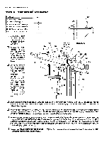
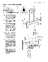
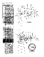
STEP 7 ARM PRESS ASSEMBLY PART NAME 71 1/4" NYLON LOCK NUT 74 114" X 3/4" ROUND HEAD SCREW 82 1" ROUND PLASTIC COVER CAP 86 1 3/4" SQUARE PLASTIC INSERT CAP 87 1" ROUND PLASTIC INSERT CAP 96 1" I.D. SPRING RETAINER RING QTY 4 4 2 6 2 Cap each end of the bottom Cross Member Tube of the ARM PRESS PIVOT FRAME (24) with 1 3/4" SQUARE PLASTIC INSERT CAPS (86). Cap the top of the Pivot Tubes with 1" ROUND PLASTIC INSERT CAPS (87). Fit a 4" LONG HALF ROUND PLASTIC PIVOT BUSHING (23) into the ARM PRESS PIVOT FRAME (24). Assemble this around the round tube welded between the Arm Press Frame. Position a second PIVOT BUSHING (23) around the tube. Place the ARM PRESS CAP (47) on top of the ARM PRESS PIVOT FRAME (24). Align the bolt holes in the Arm Press Cap with the bolt holes in the plate welded to the top side of the TOP FRAME (12). CI Bolt the assembly to the TOP FRAME (12) with four 1/4" X 3/4" ROUND HEAD SCREWS (74) by bolting down through the top of the ARM PRESS CAP (47) and then through the bolt holes in the welded plate on the Top Frame. Secure with 1/4" NYLON LOCK NUTS (71). o Remove the POWER STACK DECAL (125) from the backing sheet andposition the Decal to the front of the Cross Tube on the ARM PRESS PIVOT FRAME (24). LUBRICATE 24 N 87N 86 \ 12 2 PAGE 20 WEIDER SPORTING GOODS 23 23 87 86 125 74 47 74 O 71 24 71 71
-
 1
1 -
2
-
3
-
4
-
5
-
6
-
7
-
8
-
9
-
10
-
11
-
 12
12 -
 13
13 -
 14
14 -
 15
15 -
 16
16 -
 17
17 -
 18
18 -
 19
19 -
 20
20 -
 21
21 -
 22
22 -
23
-
24
-
25
-
26
 |
 |
