Weider E2000 English Manual - Page 12
the Cable Trap.
 |
View all Weider E2000 manuals
Add to My Manuals
Save this manual to your list of manuals |
Page 12 highlights
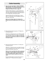
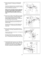
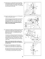
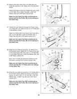
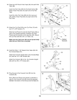
22. Remove the 3 1/2Ó Pulley (35) from the pre-assem- 22 bled Adjustment Bracket (84). Wrap the High Cable (2) around the Pulley in the direction shown. Attach the Pulley to the Bracket with a 3/8Ó x 1 1/2Ó Bolt (60) and a 3/8Ó Nylon Jamnut (63). 60 84 63 2 35 23. Wrap the High Cable (2) around a 3 1/2Ó Pulley (35) Pulley in the direction shown. Attach the Pulley (35) and two Pulley Covers (32) to the bushing below the welded hook on the Front Upright (42) with a 3/8Ó x 4 1/2Ó Bolt (93), two 3/8Ó Flat Washers (55), and a 3/8Ó Nylon Jamnut (63). Make sure the parts are assembled exactly as shown in the inset drawing. 23 Small Tabs 63 55 32 35 2 32 42 24. Locate the Low Cable (9). Wrap the end with the ball around the Low Pulley (40) in the direction shown. Attach the Low Pulley to the welded bracket on the Base (8) with a 3/8Ó x 1 1/2Ó Bolt (60) and a 3/8Ó Nylon Jamnut (63). Thread the Low Cable (9) through the Press Frame (12). Wrap the Low Cable around a 3 1/2Ó Pulley (35) in the direction shown. Attach the Pulley to the Front Upright (42) with a 3/8Ó x 3 3/4Ó Bolt (19), a Cable Trap (66), a 3/8Ó Flat Washer (55), and a 3/8Ó Nylon Jamnut (63). Make sure the Cable Trap (66) is positioned as shown and that the Pulley (35) is not rubbing on the Cable Trap. 25. Remove the pre-assembled 3 1/2Ó Pulley (35) attached to the Pulley Plates (31). Wrap the Low Cable (9) around the Pulley in the direction shown. Re-attach the Pulley (35) and a Cable Trap (66) to the lowest holes in the Pulley Plates (31) with a 3/8Ó x 1 1/2Ó Bolt (60) and the 3/8Ó Nylon Jamnut (63). 24 42 55 63 66 19 8 35 12 Welded Bracket 60 25 31 66 63 35 9 55 93 40 9 63 60 12
-
 1
1 -
2
-
3
-
4
-
5
-
6
-
 7
7 -
 8
8 -
 9
9 -
 10
10 -
 11
11 -
 12
12 -
 13
13 -
 14
14 -
 15
15 -
 16
16 -
 17
17 -
18
-
19
-
20
-
21
-
22
-
23
-
24
-
25
-
26
-
27
-
28
 |
 |
