Weider Pro 3650 English Manual - Page 6
Frame Assembly
 |
View all Weider Pro 3650 manuals
Add to My Manuals
Save this manual to your list of manuals |
Page 6 highlights
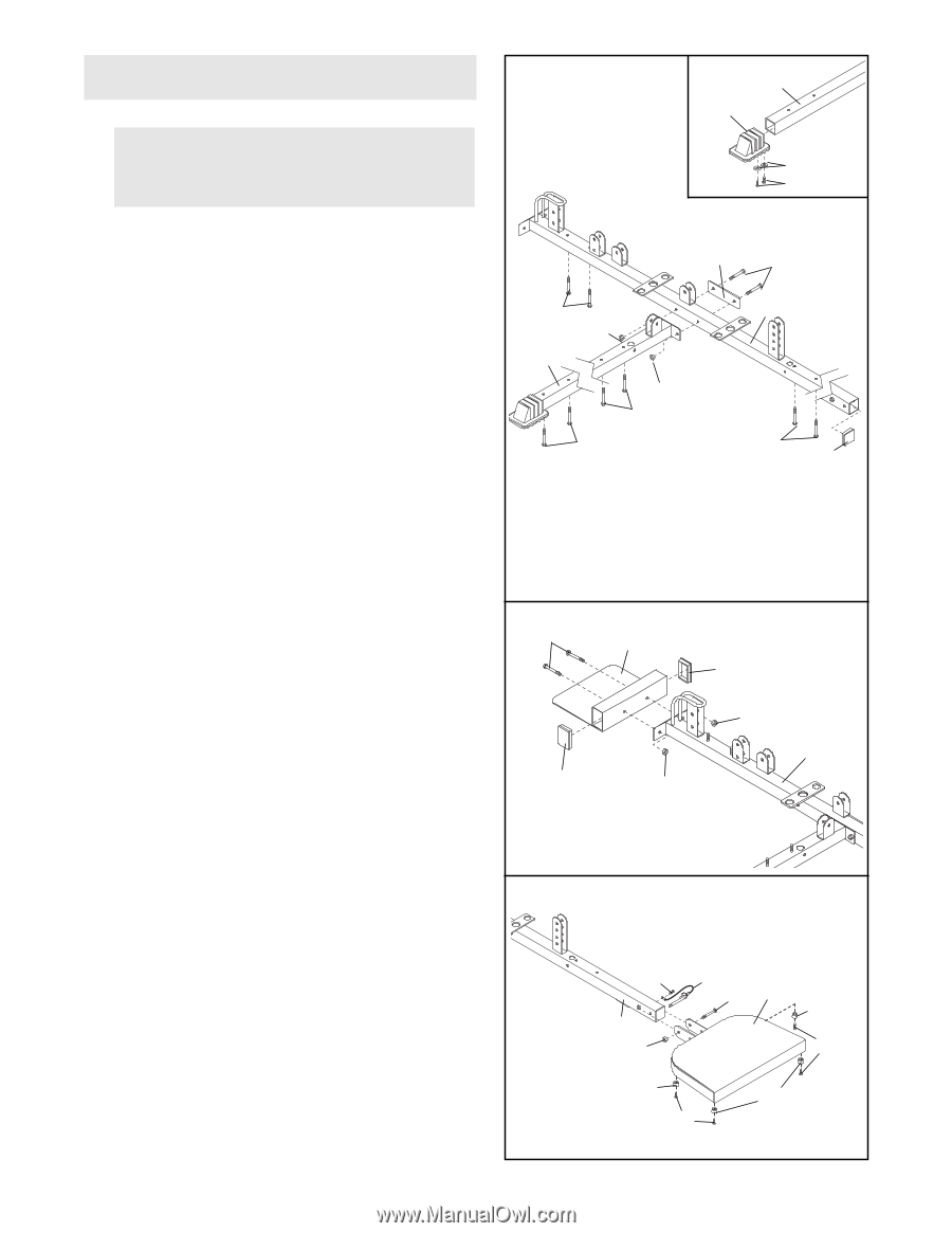
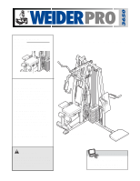
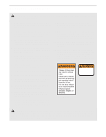
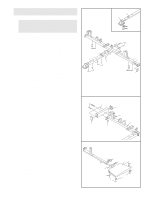
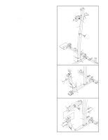
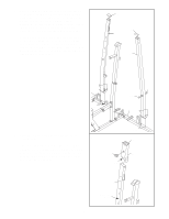
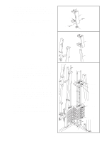
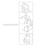
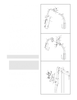
FRAME ASSEMBLY 1 1. Make sure that you understand all of the information on page 5 before you begin assembling the weight system. 2 24 120 14 Locate and open the parts bags labeled "FRAME ASSEMBLY 1" and "FRAME ASSEMBLY 2." See the inset drawing. Attach the Base Cap (24) to the Short Base (2) with two M4 x 20mm Self-tapping Screws (14) and two M4 Washers (120). Press a 50mm Square Inner Cap (105) into the open end of the Long Base (101). Insert eight M10 x 65mm Carriage Bolts (110) up through the Long Base (101) and the Short Base (2) as shown. Note: It may be helpful to place tape over the heads of the Carriage Bolts to hold them in place. Attach the Short Base (2) to the Long Base (101) with two M10 x 70mm Bolts (85), the Long Frame Plate (71), and two M10 Nylon Locknuts (87). 2. Press two 50mm x 75mm Inner Caps (58) into the Foot Plate (53). Attach the Foot Plate to the Long Base (101) with two M10 x 65mm Carriage Bolts (110) and two M10 Nylon Locknuts (87). 110 87 2 87 110 110 71 85 101 110 105 2 110 58 53 87 58 87 101 3. Attach the tether on the Long Pin w/Tether (112) to 3 the Long Base (101) with an M4 x 20mm Self-tap- ping Screw (14). Attach the four Knee Rest Bumpers (108) to the Squat Knee Rest (41) with four M4 x 20mm Selftapping Screws (14). Attach the Squat Knee Rest to the Long Base (101) with an M10 x 85mm Bolt (96) and an M10 Nylon Locknut (87). Do not overtighten the Locknut; the Squat Knee Rest must be able to pivot. 6 14 101 87 112 96 41 108 14 108 108 14
-
 1
1 -
 2
2 -
 3
3 -
 4
4 -
 5
5 -
 6
6 -
 7
7 -
 8
8 -
 9
9 -
 10
10 -
 11
11 -
 12
12 -
13
-
14
-
15
-
16
-
17
-
18
-
19
-
20
-
21
-
22
-
23
-
24
-
25
-
26
-
27
-
28
-
29
-
30
-
31
-
32
-
33
 |
 |