Weider Pro 5000 Uk Manual - Page 13
Lever 7. Slide two Foam Pads 21 onto the Pad
 |
View all Weider Pro 5000 manuals
Add to My Manuals
Save this manual to your list of manuals |
Page 13 highlights
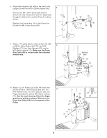
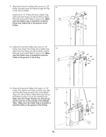
20. Attach the Seat (19) to the Seat Frame (6) with two M6 x 16mm Screws (60), an M6 x 77mm 20 Screw (68), and an M6 Washer (78). 19 Hook the Seat Frame (6) onto the Upright (3) at the indicated location. 3 6 78 60 68 21. Attach the Bumper (49) to the Leg Lever (7) with the M4 x 16mm Screw (70). 21 Apply grease to an M10 x 71mm Bolt (67). Attach the Leg Lever (7) to the Seat Frame (6) with the Bolt and an M10 Nylon Locknut (73). Do not overtighten the Bolt; the Leg Lever must be able to pivot easily. Grease 67 73 7 6 49 70 22. Slide two Foam Pads (21) onto the Seat Frame (6). 22 Slide a Pad Tube (20) through a hole in the Leg Lever (7). Slide two Foam Pads (21) onto the Pad Tube. 6 21 7 21 21 20 21 23. Make sure that all parts have been properly tightened before the resistance system is used. 13
-
 1
1 -
2
-
3
-
4
-
5
-
6
-
7
-
 8
8 -
 9
9 -
 10
10 -
 11
11 -
 12
12 -
 13
13 -
 14
14 -
 15
15 -
 16
16 -
 17
17 -
 18
18 -
19
-
20
-
21
-
22
-
23
-
24
 |
 |
