Weider Pro 545 English Manual - Page 12
Attach the other U Bracket to Top Frame A - cable
 |
View all Weider Pro 545 manuals
Add to My Manuals
Save this manual to your list of manuals |
Page 12 highlights
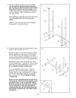
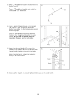
19. Attach each section of the Top Frame (21, 39) to the Front Uprights (18) with an M8 x 68mm Bolt (8), two M8 Washers (13), and an M8 Nylon Locknut (12). Attach each section of the Top Frame (21, 39) to the Rear Uprights (19) with two M8 x 68mm Bolts (8), two M8 Washers (13), and two M8 Nylon Locknuts (12). Tighten all Nylon Locknuts and Bolts used in steps 11-19. 20. Attach a Cable (51) to one of the Weight Carriages (52) with an M10 x 75mm Bolt (10), two Cable Spacers (45), and an M10 Nylon Locknut (14). Attach the other Cable to the other Weight Carriage (not shown) in the same manner. 19 8 13 21 8 18 20 39 8 12 13 12 19 18 12 8 13 45 51 45 10 14 13 19 12 52 21. Lubricate an M10 x 90mm Bolt (7). Attach a "U" Bracket (30) to Top Frame B (39) with the Bolt and 21 an M10 Nylon Locknut (14). Do not overtighten the Nylon Locknut. Attach the other "U" Bracket to Top Frame A (not shown) in the same manner 39 7-Lubricate 22. Wrap the indicated Cable (51) around a Pulley (24). Attach the Pulley to the "U" Bracket (30) with an 22 M10 x 48mm Bolt (9), a Cable Trap (23), and an M10 Nylon Locknut (14). The Cable must be rout- ed around the Pulley from the direction shown. The Cable Trap should be attached on the out- side of the "U" Bracket and should be turned to hold the Cable in place. Assemble the other Pulley to the other "U" Bracket (not shown) in the same manner. 14 30 14 23 9 24 30 51 12
-
 1
1 -
2
-
3
-
4
-
5
-
6
-
 7
7 -
 8
8 -
 9
9 -
 10
10 -
 11
11 -
 12
12 -
 13
13 -
 14
14 -
 15
15 -
 16
16 -
 17
17 -
18
-
19
-
20
-
21
-
22
-
23
-
24
 |
 |
