Weider Pro 545 English Manual - Page 7
en the Nylon Locknut; the Backrest Brackets
 |
View all Weider Pro 545 manuals
Add to My Manuals
Save this manual to your list of manuals |
Page 7 highlights
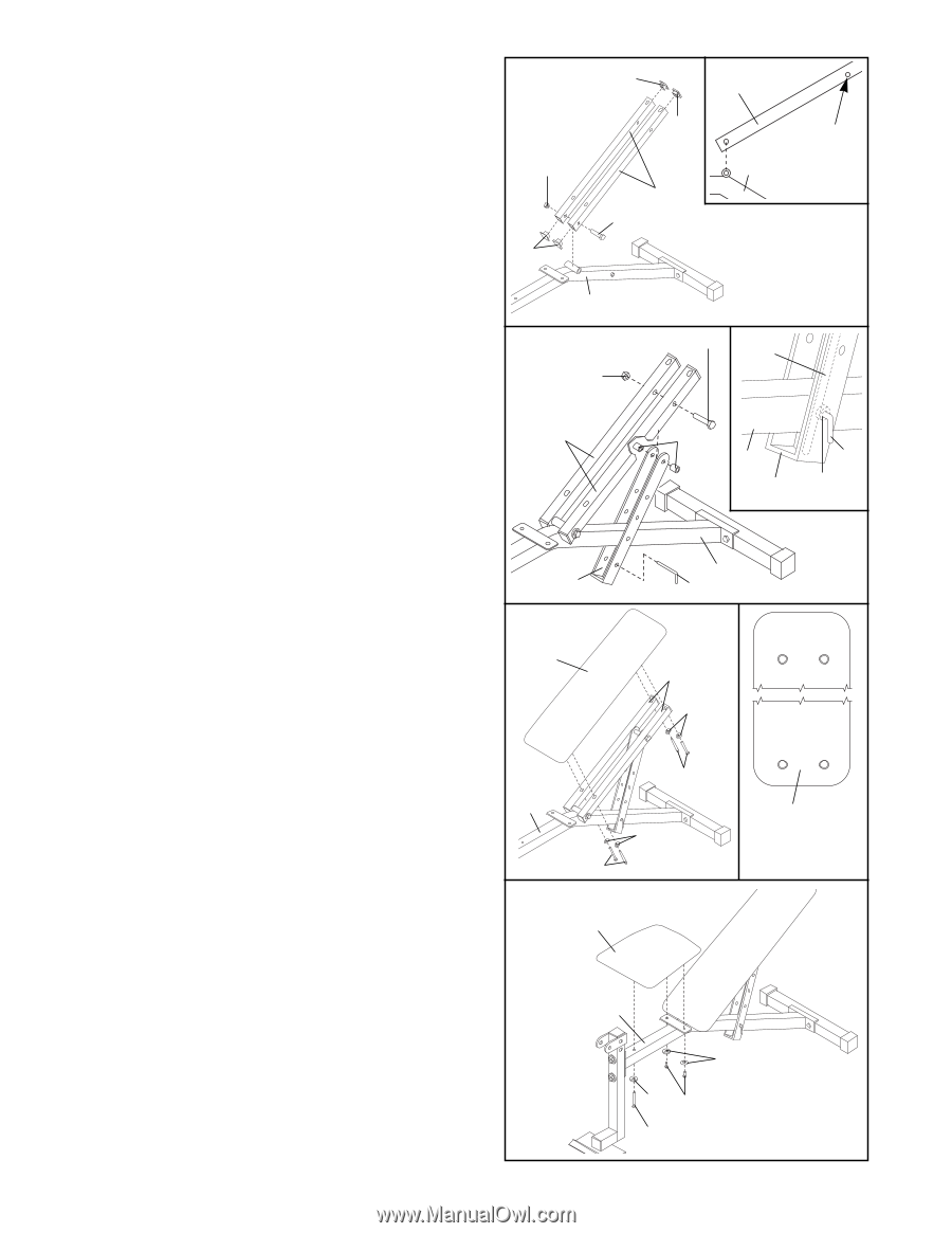
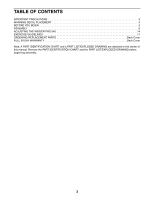
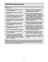
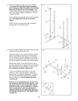
3. Press 20mm x 40mm Inner Caps (44) into the ends of both Backrest Tubes (25). Lubricate an M10 x 152mm Bolt (11). Attach the Backrest Tubes (25) to the Bench Frame (49) with the Bolt and an M10 Nylon Locknut (14). See the inset drawing. The indicated hole in the Backrest Tube (25) is slightly off center. The Backrest Tube must be oriented as shown, when it is attached to the Bench Frame (49). Do not overtighten the Nylon Locknut; the Backrest Brackets must be able to move freely. 4. Slide the Adjustment Bracket (26) onto the Bench Frame (49). See the inset drawing. The guide rod inside the Adjustment Bracket must be on the indicated side of the welded tube in the Bench Frame. Align one set of holes in the Adjustment Bracket (26) with the hole in the Bench Frame (49). Insert the "L" Pin (46) through the Adjustment Bracket and the Bench Frame. Lubricate an M10 x 152mm Bolt (11). Attach the Adjustment Bracket (26) to the Backrest Tubes (25) with the Bolt, two Adjustment Bracket Spacers (50), and an M10 Nylon Locknut (14). Do not overtighten the Nylon Locknut; the Backrest Brackets and Adjustment Bracket must be able to move freely. 5. Attach the Backrest (29) to the Backrest Tubes (25) with four M6 x 48mm Screws (35) and four M6 Washers (42). Note: Before you attach the Backrest to the Backrest Tubes, look at the back side of the Backrest. You will notice that one set of threaded holes is closer to the end of the Backrest (see the inset drawing). This end of the Backrest must be closest to the Bench Frame (49). 6. Attach the Seat (34) to the Bench Frame (49) with the M6 x 60mm Screw (16), two M6 x 16mm Screws (17), and three M6 Washers (42). 3 14 44 44 25 44 49 25 11-Lubricate Hole must be on the lower side 49 4 Lubricate-11 Guide Rod 14 25 50 49 46 26 Welded Tube 26 5 29 49 46 25 42 35 49 42 35 6 34 This end of the Backrest must be closest to the Bench Frame 49 42 42 17 16 7
-
 1
1 -
 2
2 -
 3
3 -
 4
4 -
 5
5 -
 6
6 -
 7
7 -
 8
8 -
 9
9 -
 10
10 -
 11
11 -
 12
12 -
13
-
14
-
15
-
16
-
17
-
18
-
19
-
20
-
21
-
22
-
23
-
24
 |
 |