Weider Pro 545 English Manual - Page 9
Locknut. Note: The heads of the Carriage Bolts - assembly
 |
View all Weider Pro 545 manuals
Add to My Manuals
Save this manual to your list of manuals |
Page 9 highlights
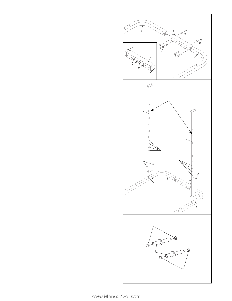
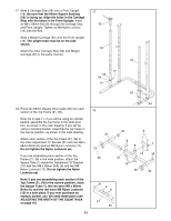
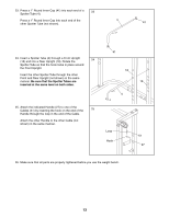
11. Note: The WEIDER PRO 545 is designed to be used with both olympic and standard barbells. If you will be using an olympic barbell, assemble the base in the wide position, as shown in the main drawing. If you will be using a standard barbell, assemble the base in the narrow position, as shown in the inset drawing. Attach each section of the Base (20, 55) to an Adjustment "U" Bracket (31) with two M8 x 68mm Bolts (8) and two M8 Nylon Locknuts (12). Do not tighten the Nylon Locknuts yet. 12. Slide a Rear Upright (19) onto the indicated M8 x 58mm Carriage Bolts (6) in either section of the Base (20, 55). The Rear Upright must be oriented as shown, with the indicated holes facing forward. A second person must hold the Upright at the location shown during the step. Partially tighten an M8 Nylon Locknut (12) onto each Carriage Bolt but do not fully tighten the Nylon Locknut. Note: The heads of the Carriage Bolts must lock into the square holes in each section of the Base in order to tighten the Nylon Locknuts; you may need to slide your fingers under the Base to hold the Carriage Bolts in place while you partially tighten the Nylon Locknuts. Assemble the other Rear Upright (19) in the same manner. 11 31 12 20 12 20 31 8 8 55 8 8 55 12 A second person must hold each Upright here while the Nylon Locknuts are attached 19 19 These holes must face 12 forward 12 6 20 55 6 13. Press 1" Round Inner Caps (41) into the ends of the Weight Rests (37). 13 41 37 41 9
-
 1
1 -
2
-
3
-
 4
4 -
 5
5 -
 6
6 -
 7
7 -
 8
8 -
 9
9 -
 10
10 -
 11
11 -
 12
12 -
 13
13 -
 14
14 -
15
-
16
-
17
-
18
-
19
-
20
-
21
-
22
-
23
-
24
 |
 |