Weider Pro 545 English Manual - Page 8
into the Leg Lever. Press a 1 Angle Cap 5 onto
 |
View all Weider Pro 545 manuals
Add to My Manuals
Save this manual to your list of manuals |
Page 8 highlights
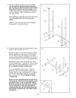
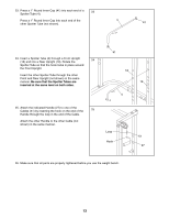
7. Press three 50mm Square Inner Caps (36) into the 7 Leg Lever (32). Press a 1" Round Inner Cap (41) into the Leg Lever. Press a 1" Angle Cap (5) onto 36 the Leg Lever. 41 8. Lubricate the M10 x 75mm Bolt (10). Attach the Leg 8 Lever (32) to the Front Leg (22) with the Bolt and an M10 Nylon Locknut (14). 14 32 32 5 36 10-Lubricate 22 9. Tap 3/4" Round Inner Caps (43) into each end of the three Pad Tubes (38). Insert a Pad Tube (38) through one hole in the Leg Lever (32). Insert another Pad Tube through the other hole in the Leg Lever. Insert the remaining Pad Tube through the upper hole in the Front Leg (22). Slide two Foam Pads (48) onto each Pad Tube (38). 10. Set each section of the Base (20, 55) on the floor. Be sure that the indented side of each section of the Base is facing the floor. Press a 50mm Square Inner Cap (36) into the indicated end of each section of the Base. Insert four M8 x 58mm Carriage Bolts (6) into each section of the Base (20, 55). 9 48 43 38 Upper Hole 48 43 43 38 22 48 43 48 32 48 38 43 10 20 6 6 55 6 36 6 The indented side must face the floor 8
-
 1
1 -
2
-
 3
3 -
 4
4 -
 5
5 -
 6
6 -
 7
7 -
 8
8 -
 9
9 -
 10
10 -
 11
11 -
 12
12 -
 13
13 -
14
-
15
-
16
-
17
-
18
-
19
-
20
-
21
-
22
-
23
-
24
 |
 |
