Weider Pro 9628 English Manual - Page 11
Make sure the Long Cable Trap 50 is
 |
View all Weider Pro 9628 manuals
Add to My Manuals
Save this manual to your list of manuals |
Page 11 highlights
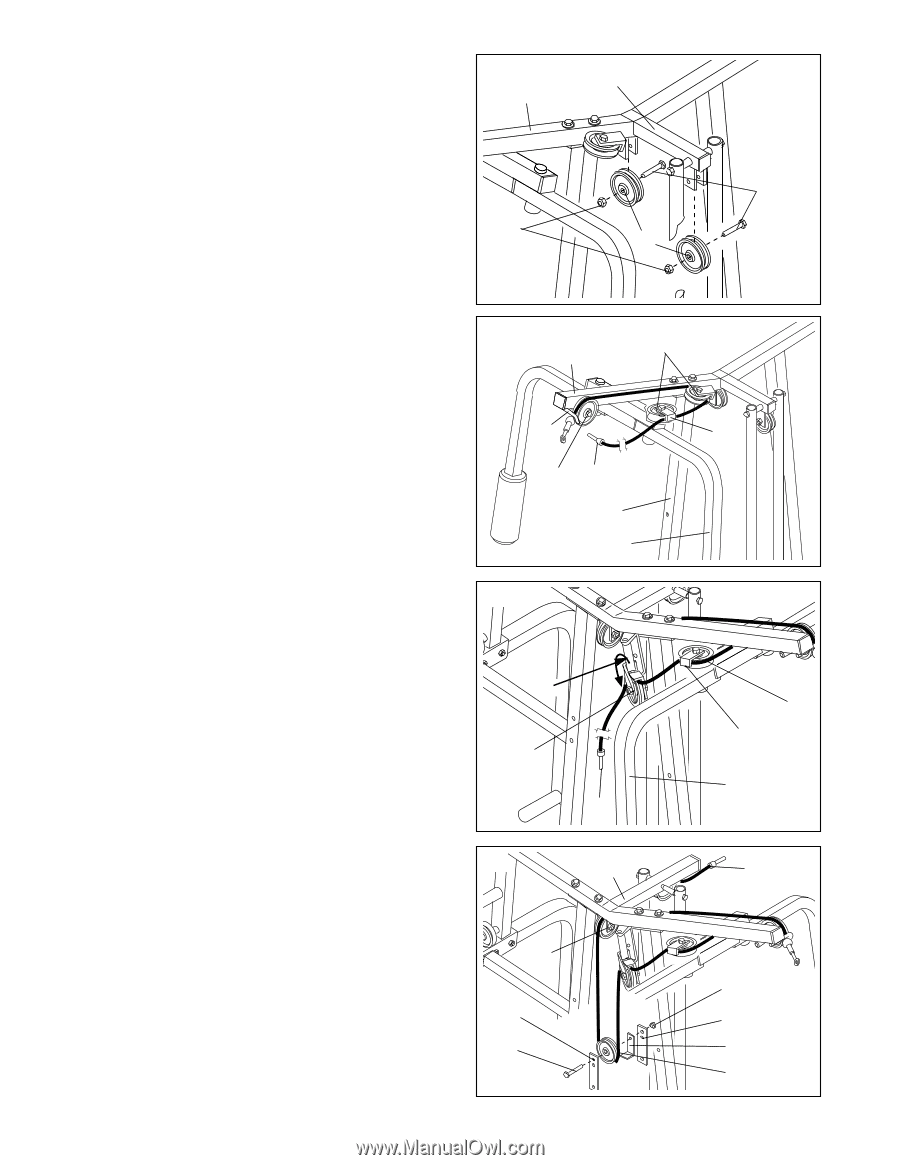
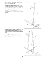
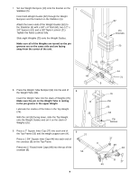
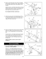
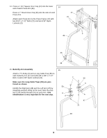
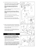
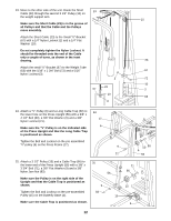
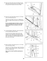
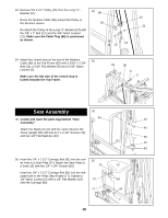
19. Attach two 3 1/2" Pulleys (15) to the weight support 19 arm (A) on the Top Frame (55) with two 3/8" x 2" A Bolts (12) and two 3/8" Nylon Locknuts (21). 55 12 21 15 20. Locate the Short Cable (23). It has a ball on one end 20 and a threaded tip on the other. Feed the threaded end of the Short Cable (23) between the pre-assembled 3 1/2" Pulley (15) and the hook (C) on the Top Frame (55). Next, route the Short Cable around the angled "V"-Pulley (6) on the Butterfly Upright (42) and then around the "V"-Pulley (6) on the Left Butterfly Arm (47). Make sure the Long Cable Trap (50) is positioned to hold the Cable in place. If necessary, adjust the position of the Long Cable Trap. 6 55 C 15 23 42 47 21. Move to the other side of the unit. Route the Short 21 Cable (23) around the "V"-Pulley (6) on the Right Butterfly Arm (48). Make sure the Long Cable Trap (50) is positioned as shown. Tighten the Bolt and Locknut on the pulley bracket (D). D Tighten the Bolt and Locknut on the pre-assembled Pulley (15) attached to the pulley bracket (D). Route 15 the Short Cable (23) around the Pulley in the direc- tion shown. Make sure the Long Cable Trap (50) is positioned to hold the Cable in place. 23 22. Attach the 3 1/2" Pulley (15) and a Cable Trap (66) to 22 the two "I"-plates (81) with a 3/8" x 2" Bolt (12) and a A 3/8" Nylon Locknut (21). Make sure the Cable Trap (66) is positioned as shown. Route the Short Cable (23) around the Pulley (15) attached to the "I"-plates in the direction shown. Route the Short Cable (23) through the first 3 1/2" Pulley (15) on the weight support arm (A). 15 81 12 11 50 6 50 48 23 21 81 66 15
-
 1
1 -
2
-
3
-
4
-
5
-
 6
6 -
 7
7 -
 8
8 -
 9
9 -
 10
10 -
 11
11 -
 12
12 -
 13
13 -
 14
14 -
 15
15 -
 16
16 -
17
-
18
-
19
-
20
-
21
-
22
-
23
-
24
-
25
-
26
-
27
-
28
 |
 |