Weider Pro 9628 English Manual - Page 8
Arm Assembly
 |
View all Weider Pro 9628 manuals
Add to My Manuals
Save this manual to your list of manuals |
Page 8 highlights
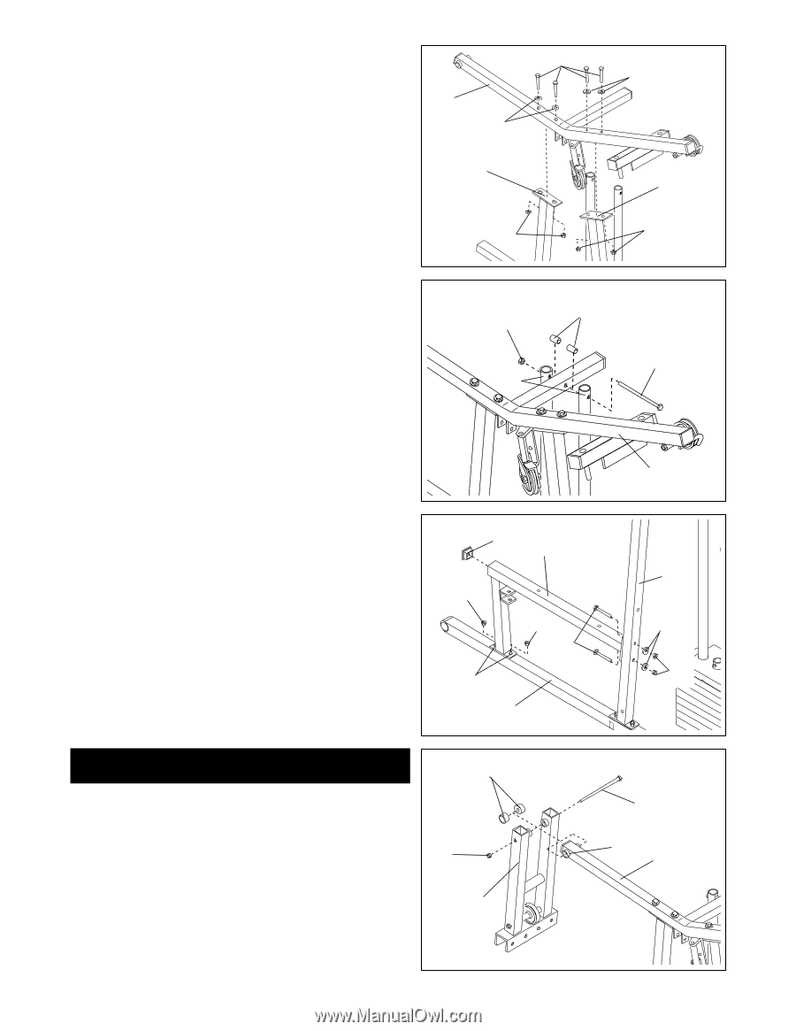
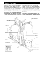
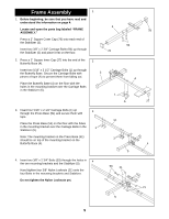
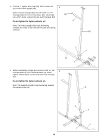
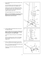
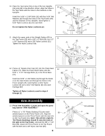
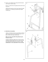
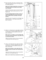
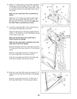
10. Place the Top Frame (55) on top of the two Uprights 10 (56) and (42) in the direction shown. Align the holes in 11 the Top Frame with the holes in the brackets on the Uprights. 55 Insert four 5/16" x 2 3/4" Bolts (11) with four 5/16" Flat Washers (8) through the holes in the Top Frame (55) and the brackets on the Uprights. Hand tighten a 5/16" Nylon Locknut (3) unto each Bolt. 8 56 Do not tighten the Nylon Locknuts yet. 3 8 42 3 11. Attach the upper ends of the Weight Guides (62) to 11 the Top Frame (55) with a 3/8" x 6" Bolt (60), two 1/2" x 3/4" Spacers (61) and a 3/8" Nylon Locknut (21). 61 21 Tighten the Nylon Locknut fully. 60 62 12. Press a 2" Square Inner Cap (27) into the Press Seat Frame (77). Slide the Press Seat Frame onto the 5/16" x 2 1/2" Carriage Bolts (1) in the Press Base (51). Insert two 5/16" x 2 3/4" Bolts (11) through the bracket on the Seat Frame and through the holes in the Press Upright (42). Hand tighten a 5/16" Nylon Locknut (3) and a 5/16" Flat Washer (8) onto each Carriage Bolt. Tighten all Nylon Locknuts used in steps 4 through 12. 12 27 77 3 3 11 1 51 55 42 8 3 Arm Assembly 13. Press Arm Assembly-Locate and open the parts bag labeled "ARM ASSEMBLY." Press a 1" x 7/8" Plastic Bushing (75) onto each welded spacer on the Press Frame (17). Align the welded spacers on the Press Frame with the tube (A) on the Top Frame (55). Note: This will be a tight fit. The Plastic Bushings should fit onto the ends of the tube on the Top Frame. Lubricate the 3/8" x 7 1/2" Bolt (59). Attach the Press Frame to the Top Frame with the Bolt and a 3/8" Nylon Jam Nut (83). 8 13 75 83 17 59 Lubricate A 55
-
 1
1 -
2
-
 3
3 -
 4
4 -
 5
5 -
 6
6 -
 7
7 -
 8
8 -
 9
9 -
 10
10 -
 11
11 -
 12
12 -
 13
13 -
14
-
15
-
16
-
17
-
18
-
19
-
20
-
21
-
22
-
23
-
24
-
25
-
26
-
27
-
28
 |
 |