Weider Ultramax 1033 Owners Manual - Page 4
Assembly
 |
View all Weider Ultramax 1033 manuals
Add to My Manuals
Save this manual to your list of manuals |
Page 4 highlights
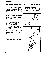
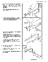
ASSEMBLY Place all parts of the weight bench in a cleared area and remove the packing materials. Do not dispose of the packing materials until assembly is completed. Read each step and look at each drawing carefully before you begin. As you assemble the weight bench, make sure that all parts are oriented exactly as shown in the drawings. Tighten all parts as you attach them, unless instructed to do otherwise. IMPORTANT: For help identifying the small parts used in assembly, remove the PART IDENTIFICATION CHART from the center of this manual. The following tools (not included) are required for assembly: Two adjustable wrenches and a standard screwdriver Lubricant, such as grease or petroleum jelly, and soapy water are also needed. • 1. Before you begin, carefully read the instructions at the top of this page and remove the PART IDENTI- 1 FICATION CHART from the center of this manual. Press two 2" Square Caps (55) into the lower end of the "H"-Frame (1). Press three 1 1/2" Square Caps (53) into the Base (2). Attach the "H"-Frame (1) to the Base (2) with the two 8mm x 60mm Bolts (31) and two 8mm 53 Locknuts (30). Do not tighten the Locknuts yet. L. 2. Attach the Main Frame (3) to the "H"-Frame (1) with tyyo8719,A_66rrnBolts (39) and two 8mr_n_,,,. 2 L0Icnuti(30)166 not fibhten the tookiiiiiiyet. Attach the Main Frame (3) to the Base (2) with an 8mm x 55mm Bolt (39) and an 8mm Locknut (30). Tighten all 8mm Locknuts (30) used in steps 1 and 2. 1 *-30 55 30 31 2 53 30 1 3 2 .1 • 3.- Attach the Backrest Brackets (6) to the Backrest (4) with four 6mm x 20mm Screws (41). Be sure 3 that the Backrest Brackets are oriented as shown. Do not tighten the Screws yet. 1N•39 41 4 6 4
-
 1
1 -
 2
2 -
 3
3 -
 4
4 -
 5
5 -
 6
6 -
 7
7 -
 8
8 -
 9
9 -
 10
10 -
11
-
12
-
13
-
14
-
15
-
16
-
17
-
18
-
19
-
20
-
21
-
22
-
23
 |
 |
