Weider Ultramax 1033 Owners Manual - Page 7
Weider Ultramax 1033 Manual
 |
View all Weider Ultramax 1033 manuals
Add to My Manuals
Save this manual to your list of manuals |
Page 7 highlights
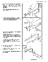
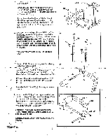
12. Insert a Plastic Sleeve (28) into the indicated welded tube on the "H"-Frame (1). 12 Apply lubricant to the axle on the Right Arm (20). Insert the axle into the Plastic Sleeve (28). Make sure that the Plastic Spacer (43) is resting against the outer side of the H-Frame (1). Secure the Right Arm by inserting a Spring Clip (51) into the end of the axle until it locks. Press a 7/8" Round Cap (36) into the indicated hole in the Right Arm (20). Attach the Left Arm (21) (not shown) in the same manner. - 13. Attach the Curl Pad (26) to the Curl Upright (27) 13 with two 6mm x 20mm Screws (41). _ a 1 20 0 Welded `I' Lubricate Tube 51 - 0 28 3 . ,i ,...43 2 4 • 14. Insert the 1/2" x 1 3/8" Metal Spacer (44) into a Pulley (17). Attach the Pulley to the Upper Mast 14 (14) with the 10mm x 45mm Bolt (48) and a 10mm Locicnut (45). Lay the Long Cable (12) in the groove in the Pulley (17). Press a 1 1/2" Square Cap (53) into the Upper Mast (14). Make sure that the Pulley and Cable can move freely. 41 27 53-9 . 17 44 45 - 48 12 14 15. Hold the Short Cable (13) in the bracket on the Lower Mast (15). 15 Insert the 1/2" x 3/4" Metal Spacer (49) into a Pulley (17). Attach the Pulley to the bracket on the Lower Mast (15) with the 10mm x 3.,qrnm Bolt (47) and a 10mm Locknut (45). Make sure that the Pulley and Cable can move freely. ; Insert a Cable Clip (33) into the lower end of the Short Cable (13). : 15 45-* 13 1.7 . c:)--49 i---47 33
-
 1
1 -
 2
2 -
 3
3 -
 4
4 -
 5
5 -
 6
6 -
 7
7 -
 8
8 -
 9
9 -
 10
10 -
 11
11 -
 12
12 -
13
-
14
-
15
-
16
-
17
-
18
-
19
-
20
-
21
-
22
-
23
 |
 |
