Weslo Cadence G-40 Treadmill English Manual - Page 11
Bolt 82, two M8 Flat Washers 72, and an M8 - walking belt
 |
View all Weslo Cadence G-40 Treadmill manuals
Add to My Manuals
Save this manual to your list of manuals |
Page 11 highlights
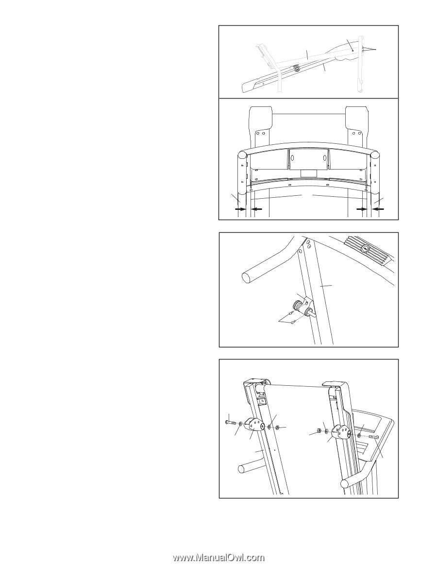
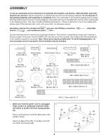
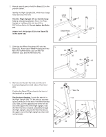
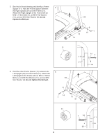
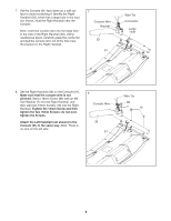
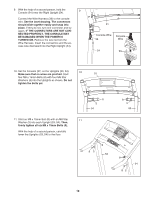
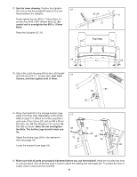
12. See the lower drawing. Position the Uprights (53, 54) so that the treadmill Frame (51) is cen- 12 tered between the Uprights. Firmly tighten the two M10 x 110mm Bolts (1) and the four M10 x R0710Amm Bolts (2). Be careful not to overtighten the M10 x 110mm Bolts. Raise the Uprights (53, 54). 1 53, 54 2 51 Top View 54 51 53 13. Attach the Latch Housing (48) to the Left Upright (53) with two #10 x 1" Screws (58); start both 13 Screws, and then tighten both of them. 53 48 58 14. Raise the treadmill to the storage position (see HOW TO FOLD THE TREADMILL FOR STORAGE on page 17). Attach an Incline Leg (95) to each side of the Frame (51) with an M8 x 52mm Bolt (82), two M8 Flat Washers (72), and an M8 Nut (46) as shown. Note: Do not overtighten the Nuts. The Incline Legs should rotate easily. Adjust the Incline Legs (95) to the desired incline (see page 16). Lower the treadmill (see page 18). 14 82 72 95 51 72 72 46 46 95 72 82 15. Make sure that all parts are properly tightened before you use the treadmill. Keep the included hex keys in a secure place. One of the hex keys is used to adjust the walking belt (see page 20). To protect the floor or carpet, place a mat under the treadmill. 11
-
 1
1 -
2
-
3
-
4
-
5
-
 6
6 -
 7
7 -
 8
8 -
 9
9 -
 10
10 -
 11
11 -
 12
12 -
 13
13 -
 14
14 -
 15
15 -
 16
16 -
17
-
18
-
19
-
20
-
21
-
22
-
23
-
24
-
25
-
26
-
27
-
28
 |
 |