Weslo Gym 1000 Uk Manual - Page 8
Cable Assembly
 |
View all Weslo Gym 1000 manuals
Add to My Manuals
Save this manual to your list of manuals |
Page 8 highlights
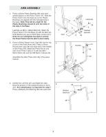
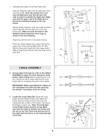
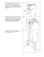
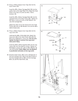
7. Lubricate both axles on the Top Frame (55). Slide the Right Arm (48) onto the right axle of the Top Frame (55). Note: Be careful not to confuse the Right Arm with the Left Arm (47); refer to step 6 to identify the Right Arm. Make sure that the upper end of the Right Arm is behind the indicated bracket on the Top Frame. Tap two 25mm Retainers (63) and a 25mm Round Cover Cap (62) onto the right axle of the Top Frame (55). Make sure that the teeth on the Retainers bend toward the Cover Cap, as shown in the inset drawing. Attach the Left Arm (47) in the same manner. Press two 45mm Square Inner Caps (44) into the lower ends of the Left and Right Arms (47, 48). Wet the lower end of each Arm with soapy water. Slide a Large Foam Pad (45) onto the lower end of each Arm. 7 48 44 45 CABLE ASSEMBLY 8. During steps 9 through 22, refer to the CABLE DIAGRAM on page 19 of this manual to verify proper cable routing. Before beginning this section, identify the Short Cable (23) and the Long Cable (58) by comparing the ends of the cables. IMPORTANT: Whilst assembling the cables, do not overtighten the bolts and nuts securing the pulleys. The pulleys must turn freely. 8 23 58 55 47 Bracket Lubricate Axle 63 62 45 55 63 62 9. Locate the Long Cable (58). Route the Long Cable around a 90mm Pulley (15). Attach the 9 Pulley and two Pulley Covers (73) to the Top Frame (55) with an M10 x 97mm Bolt (16) and an M10 Nylon Locknut (21). Note: The small tabs on the Pulley Covers must be on top. Make sure that the Cable is between the Pulley and the rod on the Top Frame and that the end of the Cable with the ball is on the indicated side of the Rod. Small 58 21 73 Tabs 55 Rod Ball 15 73 16 8
-
 1
1 -
2
-
 3
3 -
 4
4 -
 5
5 -
 6
6 -
 7
7 -
 8
8 -
 9
9 -
 10
10 -
 11
11 -
 12
12 -
 13
13 -
14
-
15
-
16
-
17
-
18
-
19
-
20
-
21
-
22
-
23
-
24
-
25
-
26
-
27
 |
 |
