Whirlpool GZ7930XHS Installation Guide - Page 7
Warning
 |
UPC - 050946738802
View all Whirlpool GZ7930XHS manuals
Add to My Manuals
Save this manual to your list of manuals |
Page 7 highlights
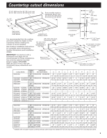
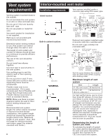
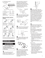
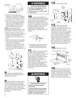
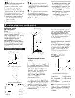
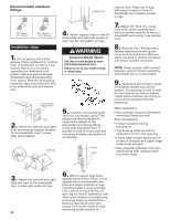
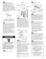
6" (15.2 cm) round vent system 90° elbows 6 ft. (1.8 m) transition 2 ft. (0.6 m) Maximum length = 35 ft. (8.9 m) 1 - wall cap = 0 ft. (0 m) 8 ft. (2.4 m) straight = 8 ft. (2.4 m) 2 - 90° elbows = 10 ft. (3 m) Transition = 4.5 ft. (1.4 m) Length of 6" (15.2 cm) system = 22.5 ft. (6.8 m) Recommended standard fittings 3-1/4" x 10" (8.3 cm x 25.4 cm) to 6" (15.2 cm) = 4.5 ft. (1.4 m) 6" (15.2 cm) to 3-1/4" x 10" (8.3 cm x 25.4 cm) = 1 ft. (0.3 m) 3-1/4" x 10" (8.3 cm x 25.4 cm) to 6" (15.2 cm) 90° elbow = 5 ft. (1.5 m) 6" (15.2 cm) to 3-1/4" x 10" (8.3 cm x 25.4 cm) 90° elbow = 5 ft. (1.5 m) 90° elbow = 45° elbow = 6" wall cap = 5 ft. (1.5 m) 2.3 ft. (0.8 m) 0 ft. (0 m) Installation steps WARNING Excessive Weight Hazard Use two or more people to move and install downdraft vent. Failure to do so can result in back or other injury. 1. Put on gloves and safety glasses. Place cardboard or another form of protection on top of a flat surface where you can easily assemble the downdraft vent system. Remove parts packages, downdraft vent and blower box from carton and set on protective surface. Remove all shipping materials, tape and protective film from downdraft vent and blower box. over counter support arm 2. Attach the left side and right side overcounter support brackets to the downdraft. Use 1 screw with each bracket. end cap 3. Attach the left side and right side end caps to the downdraft. Use 1 screw with each end cap. support leg 4. Attach support legs to side of downdraft vent with 2 screws in each leg. Do not tighten screws. 5. Carefully insert downdraft vent into countertop cutout. Two people are recommended to support the weight of the downdraft vent during lifting. Check that downdraft vent is parallel to side of cutout and that mounting brackets overlap countertop. level mark 6. Move support legs down against cabinet floor. Place a level against front of downdraft vent base and adjust until downdraft vent is level vertically. Use a pencil to mark the top of each leg on downdraft vent. Then mark location of support leg mounting holes on cabinet floor. Remove downdraft vent from cutout. Drill starter holes at each mounting screw location on cabinet floor. Align top of legs with pencil marks on the face of the downdraft vent. Tighten screws in legs. 7. Determine which direction (down, rear, left, or right) vent will need to run from blower vent when installed in cabinet. Down venting: Downdraft vent is shipped with blower in down venting position so no modification is required. Go to Step 8. Left or right venting: a. Remove 4 hex nuts that attach blower box to downdraft vent base. Remove blower box. b. Rotate blower box 90° to left or right so that vent blower is repositioned in the direction needed. c. Reattach blower box to downdraft vent base with 4 hex nuts. Rear venting: a. Remove 4 hex nuts that attach blower box to downdraft vent base. Remove blower box. b. Note how wiring cable is installed under plastic clips inside vent base. Then carefully remove wiring cable from plastic clips. Disconnect blower wiring cable. c. Remove 6 Phillips-head screws attaching blower to blower box. Remove blower. 7
-
 1
1 -
 2
2 -
 3
3 -
 4
4 -
 5
5 -
 6
6 -
 7
7 -
 8
8 -
 9
9 -
 10
10 -
 11
11 -
 12
12 -
13
-
14
-
15
-
16
-
17
-
18
-
19
-
20
-
21
-
22
-
23
-
24
-
25
-
26
-
27
-
28
-
29
-
30
-
31
-
32
 |
 |
