Whirlpool UXD8630DYS Installation Guide - Page 11
Rear Mounting-Blower Motor
 |
View all Whirlpool UXD8630DYS manuals
Add to My Manuals
Save this manual to your list of manuals |
Page 11 highlights
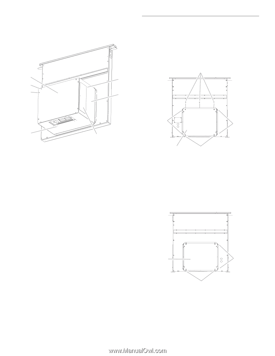
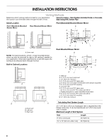
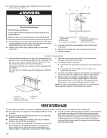
Left or Right Venting: 1. Using two or more people, place the downdraft vent system on its back. 2. Remove the 4 screws from the cover plate mounted to the face of the motor box and set them aside. A G B C F Rear Mounting-Blower Motor NOTE: Optional blower motor rear mounting position (opposite side) for island cabinet locations. The blower motor box assembly can be moved to the opposite side (rear) of the vent box. 1. Remove 7 screws from the mounting flanges of the blower motor box. Front View A A A D E A. Cover plate B. Cover plate screws (4) C. Cover plate keyhole slot shoulder screws (4) D. Motor mounting screws (4) E. Vent cover plate F. Motor box G. Vent cover screws (3) 3. Slide the cover plate up and slip it over the keyhole slot shoulder screws. Set the cover aside. 4. Remove 4 screws from the bottom of the motor box that hold the motor assembly to the motor box. NOTE: Disconnect the electrical wiring connection from motor if needed. 5. Remove 3 screws and the vent cover plate from the left or right side of the motor box for the venting direction to be used. 6. Rotate the blower motor assembly 90 degrees to the left or right side to the chosen venting direction and secure to the blower box with motor mounting screws previously removed. Do not twist or bind the wires. 7. Install the vent cover plate over the rectangular opening in the bottom of the motor box and secure with vent cover screws. NOTE: Reinstall the electrical wiring connection to motor if removed. 8. Reinstall the cover plate to the face of the motor box and secure with 4 cover plate screws previously removed. 9. For mounting the blower motor to the back of the vent box, go to the "Rear Mounting-Blower Motor" section. Otherwise, go to the "Complete Installation" section. C B A. Screws (7) B. Keyhole slot shoulder screws (2) C. Blower motor box 2. Lift blower motor box off the shoulder screws in the keyhole slots. Disconnect wire connection from blower motor and set blower motor box aside. 3. Remove 6 screws from the mounting flange of the ¼" (6.4 mm) deep cover. Rear View C A B A. Screws (6) B. Keyhole slot shoulder screws (2) C. ¼" (6.4 mm) deep cover 11
-
 1
1 -
2
-
3
-
4
-
5
-
 6
6 -
 7
7 -
 8
8 -
 9
9 -
 10
10 -
 11
11 -
 12
12 -
 13
13 -
 14
14 -
 15
15 -
 16
16 -
17
-
18
-
19
-
20
-
21
-
22
-
23
-
24
-
25
-
26
-
27
-
28
-
29
-
30
-
31
-
32
-
33
-
34
-
35
-
36
 |
 |