Whirlpool UXD8630DYS Installation Guide - Page 14
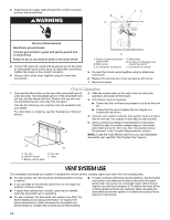
Vent System Use
 |
View all Whirlpool UXD8630DYS manuals
Add to My Manuals
Save this manual to your list of manuals |
Page 14 highlights
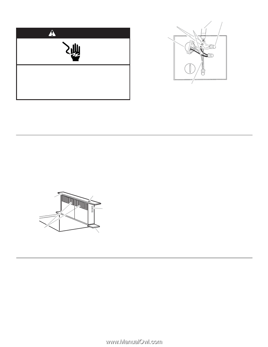
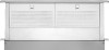
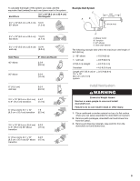
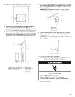
2. Feed the power supply cable through the conduit connector and into the terminal box. WARNING B D E FC Electrical Shock Hazard Electrically ground blower. Connect ground wire to green and yellow ground wire in terminal box. Failure to do so can result in death or electrical shock. 3. Connect the green (or green/yellow) ground wire to the green or yellow/green ground wire using UL listed wire connectors. Tighten the screw on the conduit connector. 4. Connect the 2 white wires together using UL listed wire connectors. A A. Green or green and yellow ground wire B. White wires C. UL listed wire connectors D. Black wires E. UL listed or CSA approved conduit connector F. Downdraft vent wiring 5. Connect the 2 black wires together using UL listed wire connectors. 6. Replace the terminal box cover and secure with screw. 7. Reconnect power. Check Operation 1. Push and hold the button on the top of the downdraft vent for a few seconds. The retractable section of the downdraft vent will rise, and the blower will start. Position the top trim over the retractable section and snap trim into place. Trim kits for matching your cooktop color are available from your dealer. For information on ordering, see the "Assistance or Service" section. B A C 2. Slide the control slider on the side of vent to check the operation and speed of the blower. 3. If the blower does not operate: ■ Check that filter or filters are pressed in as far as they will go. ■ Check that the circuit breaker has not tripped or a household fuse blown. 4. Connect vent system to blower. Vent system must end with a wall or roof cap. Use clamps or duct tape to seal all joints. 5. Install cooktop according to manufacturer's instructions. Check that rear of cooktop overlaps edge of retractable downdraft vent by ³⁄₈" (9.5 mm). See "Countertop Cutout Dimensions" in the "Location Requirements" section. NOTE: To get the most efficient use from your new retractable downdraft vent, read the "Vent System Use" section. E D A. Top trim B. ON/OFF button C. Blower control slider D. End cap E. Filters VENT SYSTEM USE The retractable downdraft vent system is designed to remove smoke, cooking vapors and odors from the cooktop area. ■ For best results, the vent should be operating before cooking is started. ■ If you use large or tall utensils, place them on the large rear element or burner surface. ■ A higher heat setting than normally used may be needed when the downdraft vent is operating. ■ For gas cooktops, the downdraft vent system may affect the flame stability and cooking performance. To improve the burner performance, either decrease the downdraft vent blower speed or increase the cooktop burner flame setting. ■ For gas cooktops with flame sensing ignitions, the downdraft vent system may disperse the flame away from the spark igniter and may cause it to continually spark while trying to reignite a burner that is already lit. To resolve the issue of the cooktop igniter continuously sparking, either decrease the downdraft vent blower speed or increase the cooktop flame setting for that burner. 14
-
 1
1 -
2
-
3
-
4
-
5
-
6
-
7
-
8
-
 9
9 -
 10
10 -
 11
11 -
 12
12 -
 13
13 -
 14
14 -
 15
15 -
 16
16 -
 17
17 -
 18
18 -
 19
19 -
20
-
21
-
22
-
23
-
24
-
25
-
26
-
27
-
28
-
29
-
30
-
31
-
32
-
33
-
34
-
35
-
36
 |
 |