Whirlpool WGD7500GC W10240504 - Page 15
All Dryers
 |
View all Whirlpool WGD7500GC manuals
Add to My Manuals
Save this manual to your list of manuals |
Page 15 highlights
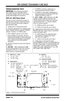
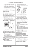
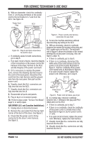
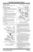
FOR SERVICE TECHNICIAN'S USE ONLY 9. Reassemble all parts and panels. 10. Plug in dryer or reconnect power. 11. Perform steps under "Service Test Mode", page 6, to verify repair. Pulley TEST #3: Motor Circuit This test will check the wiring to the motor and the motor itself. The following items are part of this motor system: Part of Motor System Harness/connection Thermal fuse Belt/belt switch Drive motor Centrifugal switch Door switch Machine control electronics (See ESD information, page 1) Electric Dryer ü ü Gas Dryer ü ü Drum Belt Figure 7 - Slowly remove drum belt. 5. Remove the white connector from the drive motor switch. See figure 8. White Drive Motor Switch Connector 264 3 5 1 NOTE: Refer to strip circuit on page 23 to diagnose drive motor. 1. Unplug dryer or disconnect power. 2. Access the machine control electronics, remove connectors P8 and P9, and measure the resistance across P8-4 and P9-1. If resistance across P8-4 and P9-1 is in the range of 1 to 6 Ω, replace the machine control electronics. Otherwise, go to step 3. 3. Check the wiring and components in the path between these measurement points by referring to the appropriate wiring diagram (gas or electric), pages 24 or 25. ALL DRYERS: Check the thermal fuse. See TEST #4b, page 19. Continue with step 4 below to test the remaining components in the motor circuit. 4. Check the belt switch and drive motor. Access the belt switch and drive motor by removing the back panel screws (to remove console, top panel, toe panel, and front panel/ drum assembly). Slowly remove the drum belt from the spring-loaded belt switch pulley, gently letting the belt switch pulley down. See figure 7. Figure 8 - Remove white connector. Main Winding: Between Pin 5 and Double Copper Wire Flag Terminal Star t Winding: Between Pin 3 and Double Copper Wire Flag Terminal 26 4 3 5 1 Belt Switch Pulley Belt Switch Blue Wires Figure 9 - Main and start winding measure points and checking the belt switch. DO NOT REMOVE OR DESTROY PAGE 15
-
 1
1 -
2
-
3
-
4
-
5
-
6
-
7
-
8
-
9
-
 10
10 -
 11
11 -
 12
12 -
 13
13 -
 14
14 -
 15
15 -
 16
16 -
 17
17 -
 18
18 -
 19
19 -
 20
20 -
21
-
22
-
23
-
24
-
25
-
26
-
27
-
28
-
29
-
30
-
31
-
32
-
33
-
34
-
35
-
36
-
37
-
38
-
39
-
40
-
41
-
42
-
43
-
44
-
45
-
46
-
47
-
48
-
49
-
50
-
51
-
52
-
53
-
54
-
55
-
56
 |
 |
