Whirlpool WGD7500GC W10240504 - Page 22
TEST #7: Door Switch, TEST #8: Drum Light
 |
View all Whirlpool WGD7500GC manuals
Add to My Manuals
Save this manual to your list of manuals |
Page 22 highlights
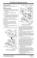
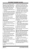
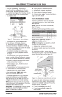
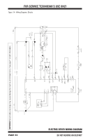
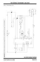
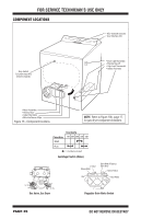
FOR SERVICE TECHNICIAN'S USE ONLY Some buttons do not light: 1. Unplug dryer or disconnect power. 2. Remove console to access the ACU and user interface (UI). 3. Replace the UI and housing assembly. 4. Reassemble all parts and panels. 5. Plug in dryer or reconnect power. 6. Perform the "Key Activation & Encoder Test" (see page 6) to verify repair. No beep sound is heard: 1. Verify that the "Signal", "Audio Level", or "Cycle Signal" volume is turned on. Press the SIGNAL, AUDIO LEVEL, or CYCLE SIGNAL button to adjust the volume level. 2. Unplug dryer or disconnect power. 3. Remove console to access the ACU and user interface (UI). 4. Visually check that ALL ACU connectors are inserted all the way into the ACU. 5. Visually check that ALL UI connectors are inserted all the way into the UI. 6. If all visual checks pass, replace the UI and housing assembly. 7. Reassemble all parts and panels. 8. Plug in dryer or reconnect power. 9. Perform the "Key Activation & Encoder Test" (see page 6) to verify repair. TEST #8: Drum Light This test is performed if the drum light does not light. 1. Unplug dryer or disconnect power. 2. Remove the console to access ACU and user interface (UI). 3. Verify that the P8 connector is securely connected to the ACU. Make sure that Pin 1 is correctly inserted. 4. Check harness and inline connections between the drum light and ACU. If the harness and connections are good, go to step 5. If not, repair or replace as needed. 5. With a voltmeter, connect black probe to ACU P8-1 (N) and red probe to P9-2 (L1) (see figure 2, page 12). Plug in dryer or reconnect power and press the POWER button. If voltage is present but the drum light does not turn on, replace the drum light bulb. If no voltage is present, open the door. If voltage is still not present, replace the ACU. 6. Reassemble all parts and panels. TEST #7: Door Switch Functionality is verified when opening the door turns on the drum light. Closing the door should turn off the drum light. If the preceding conditions are not met: 1. Unplug dryer or disconnect power. 2. Remove console to access the machine electronics. 3. Check that the wires between the door switch and ACU are connected. (Refer to wiring diagrams on pages 24 and 25.) If the connections are good, replace the wire and door switch assembly and retest. If wire and door switch assembly have been replaced and dryer still does not start, replace the ACU. 4. Reassemble all parts and panels. 5. Plug in dryer or reconnect power. 6. Verify that the dryer will start with the door closed, and that it stops when the door opens. PAGE 22 DO NOT REMOVE OR DESTROY
-
 1
1 -
2
-
3
-
4
-
5
-
6
-
7
-
8
-
9
-
10
-
11
-
12
-
13
-
14
-
15
-
16
-
 17
17 -
 18
18 -
 19
19 -
 20
20 -
 21
21 -
 22
22 -
 23
23 -
 24
24 -
 25
25 -
 26
26 -
 27
27 -
28
-
29
-
30
-
31
-
32
-
33
-
34
-
35
-
36
-
37
-
38
-
39
-
40
-
41
-
42
-
43
-
44
-
45
-
46
-
47
-
48
-
49
-
50
-
51
-
52
-
53
-
54
-
55
-
56
 |
 |
