Whirlpool WGD7500GC W10240504 - Page 7
Service Test Mode Chart - gas dryer
 |
View all Whirlpool WGD7500GC manuals
Add to My Manuals
Save this manual to your list of manuals |
Page 7 highlights
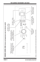
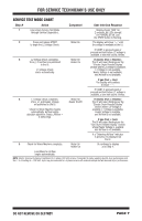
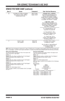
FOR SERVICE TECHNICIAN'S USE ONLY SERVICE TEST MODE CHART Step # Action Component User Interface Response 1 User enters Service Test Mode through Service Diagnostics. Display shows "888" for 2 seconds. All LEDs (except for POWER) are off, and the START button is flashing. 2 Press and release START Motor On to begin the L2 Voltage Check. The display will show "---" until the voltage is available at the UI. If START is pressed again or pressed and held before L2 voltage is available, a tone will sound 3 times. 3 L2 Voltage Check completes. Motor On Vrms_L2 and Fuel are published Heater On to the UI. L1 Voltage Check starts automatically. If electric (Fuel = Electric): The UI will report findings per the "Electric Dryer Results Display" section where L2 Voltage is available, L1 Voltage is not available, Heater Voltage is not available, and Airflow is not available. If gas (Fuel = Gas): The display will continue to show "---". If START is pressed again or pressed and held before L1 voltage is available, a tone will sound 3 times. 4 L1 voltage check completes. Motor On Vrms_L1 and Heater_Voltage Heater On/Off are published to the UI. Check for Warm Machine begins automatically. Airflow begins detection algorithm: Status_Airflow = 3 (Detecting). If electric (Fuel = Electric): The UI will report findings per the "Electric Dryer Results Display" section where L2 Voltage is available, L1 Voltage is available, Heater Voltage is available, and Airflow is not available. If gas (Fuel = Gas): The UI will report findings per the "Gas Dryer Results Display" section where Heater Voltage is available and Airflow is not available. If a "Detecting Airflow" indicator is present, it is displayed on the UI. 5 Check for Warm Machine completes. Motor On Heater On UI continues to display as in Step 4. Load Mass for Airflow begins automatically. NOTE: Electric dryer performance is optimized for 2-phase, 240 VAC service. If complaint is made regarding electric dryer performance and the L1 to L2 voltage is ~208 VAC, dryer may be connected to a 3-phase service with reduced wattage that will decrease dryer performance. DO NOT REMOVE OR DESTROY PAGE 7
-
 1
1 -
 2
2 -
 3
3 -
 4
4 -
 5
5 -
 6
6 -
 7
7 -
 8
8 -
 9
9 -
 10
10 -
 11
11 -
 12
12 -
13
-
14
-
15
-
16
-
17
-
18
-
19
-
20
-
21
-
22
-
23
-
24
-
25
-
26
-
27
-
28
-
29
-
30
-
31
-
32
-
33
-
34
-
35
-
36
-
37
-
38
-
39
-
40
-
41
-
42
-
43
-
44
-
45
-
46
-
47
-
48
-
49
-
50
-
51
-
52
-
53
-
54
-
55
-
56
 |
 |