Whirlpool WGD7500GC W10240504 - Page 18
TEST #4a: Outlet Exhaust Thermistor
 |
View all Whirlpool WGD7500GC manuals
Add to My Manuals
Save this manual to your list of manuals |
Page 18 highlights
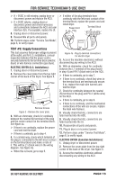
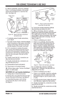
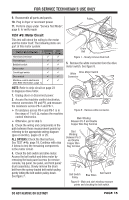
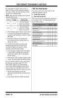
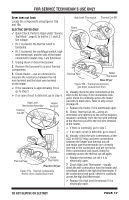
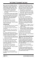
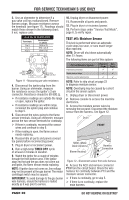
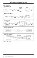
FOR SERVICE TECHNICIAN'S USE ONLY 8. If no open circuit is detected, remove the P14 connector from the ACU and measure the outlet thermistor resistance between P14-3 and P14-6 at the connector. Refer to "Outlet Thermistor Resistance" table on page 19 for temperatures and their associated values. If the resistance corresponds to the temperature, the outlet thermistor is good. Go to step 9. If the thermistor resistance does not agree with the table, replace the outlet thermistor. 9. If the preceding steps did not correct the problem and L1 and L2 were both detected, replace the ACU. If L2 was not detected, suspect the centrifugal switch before replacing the ACU. 10. Reassemble all parts and panels. 11. Plug in dryer or reconnect power. 12. Perform steps under "Service Test Mode", page 6, to verify repair. GAS DRYER ONLY: 1. Verify the gas supply to the dryer is turned on. 2. Unplug dryer or disconnect power. 3. Remove the toe panel to access thermal components. 4. Perform TEST #4c: Thermal Cut-Off on page 19. If the thermal cut-off is OK, go to step 5. 5. Locate the high limit thermostat (see figure 10b, page 17). Measure the continuity through it by connecting the meter probes to the black and light blue wire terminals. If there is an open circuit, replace both the high limit thermostat and the thermal cut-off. Otherwise, go to step 6. 6. Perform TEST #4d: Gas Valve on page 19. If the gas valve is OK, go to step 8. 7. If the preceding steps did not correct the problem, suspect the centrifugal switch before replacing the ACU. 8. Reassemble all parts and panels. 9. Plug in dryer or reconnect power. 10. Perform steps under "Service Test Mode", page 6, to verify repair. Heat will not shut off: ALL DRYERS: 1. Unplug dryer or disconnect power. 2. Remove console to access the machine electronics. 3. Remove connector P14 from the ACU and measure the resistance between P14-3 and P14-6 at the connector. Refer to "Outlet Thermistor Resistance" table on page 19 for temperatures and their associated values. If the resistance corresponds to the temperature, the outlet thermistor is good. If the thermistor resistance does not agree with the table, replace the outlet thermistor. 4. Check heater coil(s) for a short to ground (usually inside the heater box). Repair or replace if necessary. 5. Plug in dryer or reconnect power. 6. Run an "AIR" only timed dry cycle (no heat). Check heater relay output(s) on ACU. Unplug dryer or disconnect power. With a voltmeter set to AC, connect voltmeter to terminals 1 & 2 of the K2 relay at the ACU. Plug in dryer or reconnect power. Measure the voltage across terminals 1 & 2 for the K2 heater relay. If voltage is present (~240VAC for electric, ~120VAC for gas), the relay is open and working normally. If little or no voltage is present, the relay is closed and heater is activated. Unplug dryer or disconnect power and replace the ACU. 7. Unplug dryer or disconnect power. 8. Reassemble all parts and panels. 9. Plug in dryer or reconnect power. 10. Perform steps under "Service Test Mode", page 6, to verify repair. TEST #4a: Outlet (Exhaust) Thermistor NOTE: Refer to strip circuit on page 23 to diagnose the outlet temperature thermistor. The ACU monitors the exhaust temperature using the outlet thermistor, and cycles the heater relay on and off to maintain the desired temperature. NOTE: Begin with an empty dryer and a clean lint screen. 1. Unplug dryer or disconnect power. 2. Remove console to access the machine electronics. 3. Remove connector P14 from the ACU and measure the resistance between P14-3 and P14-6 at the connector. The following table on page 19 gives temperatures and their associated resistance values. PAGE 18 DO NOT REMOVE OR DESTROY
-
 1
1 -
2
-
3
-
4
-
5
-
6
-
7
-
8
-
9
-
10
-
11
-
12
-
 13
13 -
 14
14 -
 15
15 -
 16
16 -
 17
17 -
 18
18 -
 19
19 -
 20
20 -
 21
21 -
 22
22 -
 23
23 -
24
-
25
-
26
-
27
-
28
-
29
-
30
-
31
-
32
-
33
-
34
-
35
-
36
-
37
-
38
-
39
-
40
-
41
-
42
-
43
-
44
-
45
-
46
-
47
-
48
-
49
-
50
-
51
-
52
-
53
-
54
-
55
-
56
 |
 |