Yamaha DPX 1000 MCXSP10 Manual - Page 15
Connecting to a computer, DVI cable Digital - remote
 |
View all Yamaha DPX 1000 manuals
Add to My Manuals
Save this manual to your list of manuals |
Page 15 highlights
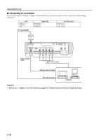
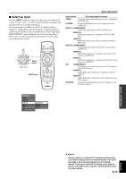
Connecting the unit I Connecting to a computer There are three ways of connecting a computer, as listed below. Please use the correct type of cable for the connector when making connections. Input INPUT A INPUT B DVI Signal type RGB Analog RGB Analog RGB Digital Connector type BNC jack x 5 D-sub 15 pin DVI connector DVI cable (Digital) DVI INPUT B RGB/YPBPR/YCBCR D4 VIDEO INPUT A OUT IN REMOTE G/Y B/PB/CB R/PR/CR HD/SYNC VD RS-232C TRIGGER OUT S-VIDEO VIDEO D-Sub monitor cable BNC monitor cable Monitor output terminal DVI output terminal Computer N Note N • Refer to see 2 in the menu described on page 19 for detailed settings for the type of image signal input. E-10
-
 1
1 -
2
-
3
-
4
-
5
-
6
-
7
-
8
-
9
-
 10
10 -
 11
11 -
 12
12 -
 13
13 -
 14
14 -
 15
15 -
 16
16 -
 17
17 -
 18
18 -
 19
19 -
 20
20 -
21
-
22
-
23
-
24
-
25
-
26
-
27
-
28
-
29
-
30
-
31
-
32
-
33
-
34
-
35
-
36
-
37
-
38
-
39
-
40
-
41
-
42
-
43
-
44
-
45
 |
 |

E-
10
DVI
INPUT B
RGB/YP
B
P
R
/YC
B
C
R
D4 VIDEO
G/Y
B/P
B
/C
B
R/P
R
/C
R
INPUT A
HD/SYNC
VD
OUT
IN
REMOTE
RS-232C
S-VIDEO
VIDEO
TRIGGER OUT
■
Connecting to a computer
There are three ways of connecting a computer, as listed below. Please use the correct type of cable for the connector when making
connections.
Connecting the unit
◆
Note
◆
•
Refer to see
2
<SIGNAL> in the menu described on page 19 for detailed settings for the type of image signal input.
DVI cable (Digital)
D-Sub monitor
cable
BNC monitor cable
Monitor output terminal
DVI output terminal
Computer
Input
INPUT A
INPUT B
DVI
Signal type
RGB Analog
RGB Analog
RGB Digital
Connector type
BNC jack x 5
D-sub 15 pin
DVI connector