Yamaha DPX 1000 MCXSP10 Manual - Page 8
Connections, S-VIDEO Mini DIN jack - hd
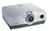 |
View all Yamaha DPX 1000 manuals
Add to My Manuals
Save this manual to your list of manuals |
Page 8 highlights
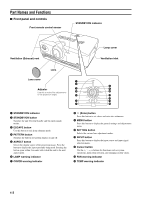
INTRODUCTION I Connections Part Names and Functions AC inlet Plug in the supplied power cord here. DVI INPUT B RGB/YPBPR/YCBCR D4 VIDEO INPUT A OUT IN REMOTE G/Y B/PB/CB R/PR/CR HD/SYNC VD RS-232C TRIGGER OUT S-VIDEO VIDEO Rear remote control sensor q w er DVI INPUT B RGB/YPBPR/YCBCR D4 VIDEO INPUT A OUT IN REMOTE G/Y B/PB/CB R/PR/CR HD/SYNC VD RS-232C TRIGGER OUT S-VIDEO VIDEO 1 2 3 4567 8 09 1 INPUT B (D-Sub 15 pin) This is the input connector for signals (RGB/YPBPR/YCBCR) from a component video or RGB source. Use a D-Sub monitor cable when connecting another component to the DPX-1000 through this connector. 2 D4 VIDEO (D connector) This connector receives video signals from the D connector of other A/V components. It is compatible with the D1-D4 formats. (This connector is designed for the Japanese D format only.) 3-7 INPUT A (BNC jacks) These are input jacks for signals from component video or RGB sources. Component signals from A/V equipment should be connected to ports 3-5, and RGB signals from Computer equipment to ports 3-7. Use a BNC cable when connecting other components to the DPX-1000 through these jacks. 3 G/Y (G, or luminance signal) 4 B/PB/CB (B, or color difference signal) 5 R/PR/CR (R, or color difference signal) 6 HD/SYNC (horizontal sync signal, composite sync signal) 7 VD (vertical sync signal) 8 S-VIDEO (Mini DIN jack) This jack receives S VIDEO signals from the S-VIDEO output jack of other A/V components. Use an S VIDEO cable when connecting other components to the DPX-1000 through this jack. 9 VIDEO (Pin jack) This jack receives composite signals from jacks of other A/V components. Use a video pin cable when connecting other components to the DPX-1000 through this jack. 0 AC inlet q DVI (DVI jack) This jack receives DVI signals from computer equipment or DVI signals from A/V equipments. w REMOTE IN/OUT jack Connect the remote control to the IN jack when using it through a cable. Codes input through the IN jack will be output directly through the OUT jack. e RS-232C (D-sub 9 pin) This jack is used for factory testing. r TRIGGER OUT This jack outputs control signals to external components. A potential of 12V/Maximum 200 mA is provided when the DPX-1000 is projecting. E-3 English
-
 1
1 -
2
-
 3
3 -
 4
4 -
 5
5 -
 6
6 -
 7
7 -
 8
8 -
 9
9 -
 10
10 -
 11
11 -
 12
12 -
 13
13 -
14
-
15
-
16
-
17
-
18
-
19
-
20
-
21
-
22
-
23
-
24
-
25
-
26
-
27
-
28
-
29
-
30
-
31
-
32
-
33
-
34
-
35
-
36
-
37
-
38
-
39
-
40
-
41
-
42
-
43
-
44
-
45
 |
 |
