Yamaha DSP-A592 Owner's Manual - Page 8
Connections, Connections With Other Components - instruction manual
 |
View all Yamaha DSP-A592 manuals
Add to My Manuals
Save this manual to your list of manuals |
Page 8 highlights
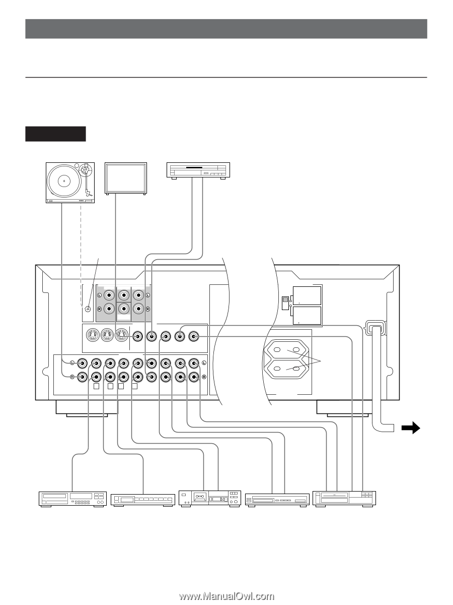
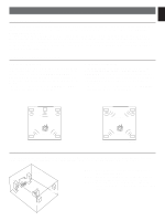
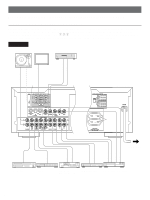
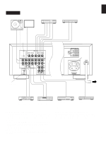
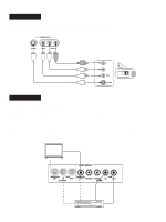
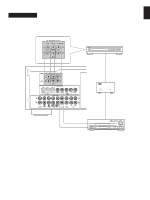
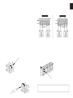
CONNECTIONS Never plug in this unit and other components until all connections are completed. CONNECTIONS WITH OTHER COMPONENTS When making connections between this unit and other components, be sure all connections are made correctly, that is to say L (left) to L, R (right) to R, "+" to "+" and "-" to "-". Also, refer to the owner's manual for each component to be connected to this unit. * If you have YAMAHA components numbered as 1, 2, 3, etc. on the rear panel, connections can be made easily by making sure to connect the output (or input) terminals of each component to the same-numbered terminals of this unit. DSP-A592 Turntable Monitor TV LD player etc. OUTPUT GND VIDEO IN AUDIO OUT VIDEO OUT 2 * GND 6CH DISCRETE INPUT DVD/LD TV/DBS MAIN CENTER SURROUND SUB WOOFER VIDEO SIGNAL MONITOR VCR OUT IN OUT S VIDEO MONITOR OUT DVD/LD TV/DBS VIDEO AUDIO SIGNAL VCR IN OUT 1 2 3 TAPE PB 4 REC OUT PHONO CD TUNER TAPE ( MD ) DVD/LD TV/DBS IN OUT VCR (Europe model) REAR (SURROUND) CENTER C DUAL SINGLE MAIN IMPEDANCE SELECTOR REAR 6ΩMIN./SPEAKER CENTER SINGLE:6ΩMIN./SPEAKER DUAL:3ΩMIN./SPEAKER MAIN A OR B:4ΩMIN./SPEAKER A B:8ΩMIN./SPEAKER REAR 8ΩMIN./SPEAKER CENTER D SINGLE:8ΩMIN./SPEAKER DUAL:4ΩMIN./SPEAKER MAIN A OR B:8ΩMIN./SPEAKER A B:I6ΩMIN./SPEAKER CAUTION SEE INSTRUCTION MANUAL FOR CORRECT SETTING. CENTER REAR (SURROUND) SUB WOOFER OUTPUT A A 1 B *B MAIN SWITCHED I00W MAX. TOTAL SPEAKERSAC OUTLETS MAINS To AC outlet OUTPUT OUTPUT LINE OUT LINE IN VIDEO OUT AUDIO OUT AUDIO OUT AUDIO IN VIDEO IN VIDEO OUT CD player Tuner Tape deck, MD recorder, etc. TV/Satellite tuner Video cassette recorder 8
-
 1
1 -
2
-
 3
3 -
 4
4 -
 5
5 -
 6
6 -
 7
7 -
 8
8 -
 9
9 -
 10
10 -
 11
11 -
 12
12 -
 13
13 -
14
-
15
-
16
-
17
-
18
-
19
-
20
-
21
-
22
-
23
-
24
-
25
-
26
-
27
-
28
-
29
-
30
-
31
-
32
-
33
-
34
 |
 |