Yamaha HTR-5490 Owner's Manual
Yamaha HTR-5490 Manual
 |
View all Yamaha HTR-5490 manuals
Add to My Manuals
Save this manual to your list of manuals |
Yamaha HTR-5490 manual content summary:
- Yamaha HTR-5490 | Owner's Manual - Page 1
U HTR-5490 AV Receiver OWNER'S MANUAL IMPORTANT Please record the serial number of this unit in the space below. MODEL: Serial No.: The serial number is located on the rear of the unit. Retain this Owner's Manual in a safe place for future reference. - Yamaha HTR-5490 | Owner's Manual - Page 2
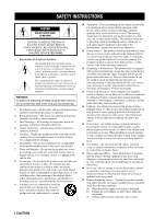
to persons. The exclamation point within an equilateral triangle is intended to alert you to the presence of important operating and maintenance (servicing) instructions in the literature accompanying the appliance. WARNING TO REDUCE THE RISK OF FIRE OR ELECTRIC SHOCK, DO NOT EXPOSE THIS UNIT TO - Yamaha HTR-5490 | Owner's Manual - Page 3
instructions. Adjust only those controls that are covered by the operating instructions as an improper adjustment of other controls SERVICE EQUIPMENT NEC - NATIONAL ELECTRICAL CODE instructions contained in this manual, meets FCC requirements. Modifications not expressly approved by Yamaha the problem - Yamaha HTR-5490 | Owner's Manual - Page 4
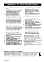
manual sounds. YAMAHA service personnel when any service is needed. The cabinet should never be opened for any reasons. 16 When not planning to use this unit for long periods of time (i.e. vacation), disconnect the AC power plug from the wall outlet. 17 Be sure to read the "TROUBLESHOOTING rear - Yamaha HTR-5490 | Owner's Manual - Page 5
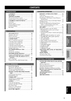
36 Automatic and Manual Tuning 37 Presetting Stations 38 Tuning in to a Preset Station 40 Exchanging Preset Stations 40 BASIC RECORDING 41 ADVANCED OPERATION REMOTE CONTROL FEATURES 42 Control Area 42 Setting the Manufacturer Code 43 Programming a New Remote Control Function (Learn Feature - Yamaha HTR-5490 | Owner's Manual - Page 6
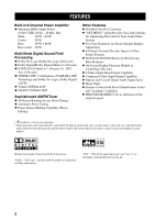
either the buttons on the main unit or on the remote control. In cases when the button names differ between the main unit and the remote control, the button name on the remote control is given in parentheses in this manual. Manufactured under license from Dolby Laboratories. "Dolby", "Pro Logic - Yamaha HTR-5490 | Owner's Manual - Page 7
China models) (Australia model) Connection Guide CONNECTION GUIDE Connection with a DVD player This connection guide shows the basic way to connect this Rear Center Rear Speaker Speaker BASIC OPERAIONT ADVANCED OPERATION ADDITIONAL INFORMATION Installing Batteries in the Remote Control - Yamaha HTR-5490 | Owner's Manual - Page 8
a 4 to 5-second delay before this unit can reproduce sound. Standby mode In this mode, this unit consumes a small amount of power to receive infrared-signals from the remote control. 2 Remote control sensor Receives signals from the remote control. 3 Front panel display Shows information about the - Yamaha HTR-5490 | Owner's Manual - Page 9
start automatic preset tuning. CONTROLS AND FUNCTIONS p TUNING MODE (AUTO/MAN'L MONO) Switches the tuning mode between automatic and manual. To select the the high-frequency or the lowfrequency sound to an extreme level, the tonal quality from the center and rear speakers may not match that of - Yamaha HTR-5490 | Owner's Manual - Page 10
for clearing functions acquired when using the learn and rename features, and set manufacturer codes (see page 46). y LEARN Used for setting up the manufacturer code or for programming the functions of other remote controls (see page 44). u SLEEP Sets the sleep timer. i 6CH INPUT Selects the source - Yamaha HTR-5490 | Owner's Manual - Page 11
DTS audio signals except for the LFE channel are also directed to the main left and right speakers. CONTROLS AND FUNCTIONS Using the Remote Control NATURAL SOUND AV RECEIVER STANDBY /ON D I G I TA L INPUT M0DE INPUT VOLUME 6CH INPUT SPEAKERS A B BASS PROCESSOR EXTENSION DIRECT TUNER DSP - Yamaha HTR-5490 | Owner's Manual - Page 12
CONTROLS up when this unit is reproducing PCM (pulse code modulation) digital audio signals. 8 Headphones indicator Lights up when headphones are connected with the sound effect (see "SILENT CINEMA DSP" on STEREO indicator Lights up when this unit is receiving a strong signal for an FM stereo broadcast - Yamaha HTR-5490 | Owner's Manual - Page 13
INTRODUCTION PREPARATION BASIC OPERAIONT Rear Panel 12 3 *1 4 CONTROLS AND FUNCTIONS 5 6 DIGITAL OUTPUT OPTICAL AUDIO R L SPEAKER A+B: 16ΩMIN. /SPEAKER CENTER : 8ΩMIN. /SPEAKER REAR CENTER: 8ΩMIN. /SPEAKER REAR : 8ΩMIN. /SPEAKER REAR CENTER AC OUTLETS 7 8 9 1 DIGITAL OUTPUT jacks 2 - Yamaha HTR-5490 | Owner's Manual - Page 14
sound plus the effect sounds. They will probably be the speakers from your present stereo system. The rear speakers are used for the effect and surround sounds, and the center speaker is for the center sounds the DTS signal is played back. The YAMAHA Active Servo Processing Subwoofer System is ideal - Yamaha HTR-5490 | Owner's Manual - Page 15
be heard from the speakers, and if the polarity of the speaker connections is incorrect, the sound will be unnatural and lack bass. CAUTION • Use speakers with the specified impedance shown on the rear panel of this unit. • Do not let the bare speaker wires touch each other and do not let - Yamaha HTR-5490 | Owner's Manual - Page 16
YAMAHA Active Servo Processing Subwoofer System, connect the input jack of the subwoofer system to this jack. Low bass signals distributed from the main, center and/or rear with the control on the subwoofer. It is also possible to adjust the volume level by using the remote control of this unit - Yamaha HTR-5490 | Owner's Manual - Page 17
of main speakers, the impedance of each speaker must be 8 Ω or higher. Left Center The impedance must be 6 Ω or higher. Rear The impedance must be 6 Ω or higher. Center Rear The impedance of each speaker must be 6 Ω or higher. IMPEDANCE SELECTOR SET BEFORE POWER ON MAIN A OR B: 4ΩMIN. /SPEAKER - Yamaha HTR-5490 | Owner's Manual - Page 18
Refer to the operation instructions for each component to be connected to this unit. • When you connect other YAMAHA audio components (such When you are using the COMPONENT VIDEO jacks, check the details in the owner's manual that came with the component being connected. I VIDEO AUX jacks (on the - Yamaha HTR-5490 | Owner's Manual - Page 19
INTRODUCTION RF OPTICAL OUTPUT OUTPUT LD player COMPONENT AUDIO OUTPUT OUTPUT TV/digital TV or LD player CONNECTIONS OPTICAL OUTPUT AUDIO OUTPUT DVD player COMPONENT OUTPUT S VIDEO OUTPUT S VIDEO V OUTPUT LR S VIDEO OUTPUT S VIDEO V OUTPUT PREPARATION BASIC OPERATION ADVANCED - Yamaha HTR-5490 | Owner's Manual - Page 20
you connect a recording component to this unit, keep its power on while using this unit. If the power is off, this unit may distort the sound from other components. • When you record from a source component connected to this unit while this unit is set in the standby mode, the recorded - Yamaha HTR-5490 | Owner's Manual - Page 21
INTRODUCTION PREPARATION BASIC OPERATION OPTICAL INPUT MD recorder or tape deck INPUT LR OUTPUT LR CONNECTIONS OPTICAL INPUT CD recorder OPTICAL OUTPUT OUTPUT O LR INPUT LR O OPTICAL OUTPUT O CD player OUTPUT L R C COAXIAL OUTPUT (U.S.A. model) DIGITAL OUTPUT OPTICAL AUDIO R - Yamaha HTR-5490 | Owner's Manual - Page 22
, sound processor or pre-amplifier. SUBWOOFER jack When using a subwoofer with built-in amplifier, including the YAMAHA Active volume level of the subwoofer with the control on the subwoofer. It is also possible to adjust the volume level by using the remote control of this unit (see ADJUSTING THE - Yamaha HTR-5490 | Owner's Manual - Page 23
components to this unit. The power to the AC OUTLET(S) is controlled by this unit's STANDBY/ON (or SYSTEM POWER and STANDBY). These 8ΩMIN. /SPEAKER REAR CENTER: 8ΩMIN. /SPEAKER REAR : 8ΩMIN. /SPEAKER AC OUTLETS I VOLTAGE SELECTOR (China model only) The VOLTAGE SELECTOR on the rear panel of this - Yamaha HTR-5490 | Owner's Manual - Page 24
are completed, turn on the power of this unit. 1 NATURAL SOUND AV RECEIVER STANDBY /ON D I G I TA L INPUT M0DE INPUT POWER AV AMP 1 Press STANDBY/ON (SYSTEM POWER on the remote control) to turn on the power of this unit. SYSTEM POWER STANDBY /ON or Front panel Remote control The - Yamaha HTR-5490 | Owner's Manual - Page 25
Make sure the AMP mode is selected and press ON SCREEN on the remote control repeatedly to change the display mode. The OSD mode changes in the CD-R D-TV/LD VCR 1 VCR2/DVR DVD SELECT POWER TV REC DISC SKIP POWER AV AMP AUDIO + VOL - LEVEL TITLE TV INPUT + TV VOL SET MENU MENU A/B/C/D/E - Yamaha HTR-5490 | Owner's Manual - Page 26
other possible settings. Summary of SPEAKER SET Items 1A through 1F Item 1A CENTER SP 1B MAIN SP 1C REAR L/R SP 1D REAR CT SP 1E LFE/BASS OUT 1F MAIN LEVEL Description Control value (default setting indicated in bold) Selects the output mode according to whether or not a center speaker is being - Yamaha HTR-5490 | Owner's Manual - Page 27
should be made at your listening position with the remote control. After completing the adjustments, use VOL +/- at your listening position to check if the adjustments are satisfactory. 3 Before You Begin NATURAL SOUND AV RECEIVER STANDBY /ON D I G I TA L INPUT M0DE INPUT PRO LOGIC VOLUME - Yamaha HTR-5490 | Owner's Manual - Page 28
SP" on the SET MENU is set to NONE, the center channel sound is automatically output from the left and right main speakers. • If "1C REAR L/R SP" on the SET MENU is set to NONE, the output level of the rear right, left and center speakers cannot be adjusted in step 4. The test - Yamaha HTR-5490 | Owner's Manual - Page 29
INTRODUCTION PREPARATION BASIC OPERATION BASIC PLAYBACK 1 4 64 NATURAL SOUND AV RECEIVER STANDBY /ON D I G I TA L INPUT PHONO TUNER CD V-AUX CBL/SAT MD/TAPE CD-R D-TV/LD VCR 1 VCR2/DVR DVD Front panel Remote control V AUX VCR2/DVR VCR 1 CBL/SAT D TV/LD DVD MD/TAPE CD R TUNER CD PHONO - Yamaha HTR-5490 | Owner's Manual - Page 30
jacks is turned off, the reproduced sound may be distorted or the volume may be lowered for the characteristics of AV receivers. In this case, turn on the component. 7 Select a DSP program if desired. Use PROGRAM l / h (DSP program buttons on the remote control) to select a DSP program. See pages - Yamaha HTR-5490 | Owner's Manual - Page 31
to select the input source on the remote control) repeatedly until the desired input mode is source that has not been digitally recorded, the sound may not be output for some LD players supports 96-kHz sampling digital signals and set the player for digital output. Refer to the operation instructions - Yamaha HTR-5490 | Owner's Manual - Page 32
, see pages 31 to 35. NATURAL SOUND AV RECEIVER STANDBY /ON D I G I TA l / h (one of the numeric buttons on the remote control) to select the desired program. The name of the selected Neo: 6 Cinema, no sound will be heard from the main speakers and the rear speakers. Sound can only be heard from - Yamaha HTR-5490 | Owner's Manual - Page 33
PRO LOGIC or Neo: 6 in the program No. 10. NATURAL SOUND AV RECEIVER STANDBY /ON D I G I TA L INPUT M0DE INPUT PRO LOGIC 1 8 MOVIE THEATER 2 9 /DTS SUR. 10 0 SELECT 11 +10 6.1/ES 12 CHP/INDEX Remote control V AUX VCR2/DVR VCR 1 CBL/SAT D TV/LD DSP PRO LOGIC / SP A DVD MD/TAPE - Yamaha HTR-5490 | Owner's Manual - Page 34
effect back on. STEREO EFFECT STEREO or EFFECT Front panel Remote control Notes • If you turn off the sound effect, no sound is output from the center speaker, rear speakers, rear center speaker and subwoofer. • If you turn off the sound effect while a Dolby Digital or DTS signal is being - Yamaha HTR-5490 | Owner's Manual - Page 35
stereo system that uses only two speakers is not capable of recreating a realistic sound field. YAMAHA's DSP requires four effect speakers to recreate sound fields based on the measured sound field data. The processor controls the strength and delay time of the signals output from the four effect - Yamaha HTR-5490 | Owner's Manual - Page 36
, Dolby Digital, and Dolby Pro Logic surround sound technologies with YAMAHA DSP sound field programs to provide the surround sound field. It recreates the most complete movie sound design in your audio room. In CINEMA-DSP sound field programs, YAMAHA's exclusive DSP processing is added to the right - Yamaha HTR-5490 | Owner's Manual - Page 37
or DTS technology. I Dolby Digital/DTS + DSP sound field effect Presence DSP sound field These programs use YAMAHA's tri-field DSP processing on each of the Dolby Digital range channels (3 channels in front and 2 or 3 channels in rear). They also provide two modes; MOVIE/ CINEMA for movies and - Yamaha HTR-5490 | Owner's Manual - Page 38
signal format, this unit automatically chooses the appropriate decoder and DSP sound field pattern. Table of Program Names for Each Input Format Input selected. • 6.1/ES on the remote control can be used to play Dolby Digital or DTS 5.1 channel sources with rear center speaker. In this case the - Yamaha HTR-5490 | Owner's Manual - Page 39
actual acoustic environments. Note • Select the DSP program that you feel sounds best regardless of the name and description given for it below. No. stadium spread on the surround side, while their spread to the rear is properly restrained. This program is provided for reproducing monaural video - Yamaha HTR-5490 | Owner's Manual - Page 40
areas, set the FREQUENCY STEP switch (locating on 50kHz/9kHz FM AM FREQUENCY STEP the rear panel) according to the frequency spacing in your area. North, Central and South America: improve the quality. Consult the nearest authorized YAMAHA dealer or service center about the outdoor antennas. 36 - Yamaha HTR-5490 | Owner's Manual - Page 41
of tuning; automatic and manual. Automatic tuning is effective when station signals are strong and there is no interference. When using the remote control to proceed some of the steps in "TUNING", make sure the "TUNER" mode is selected. 1 NATURAL SOUND AV RECEIVER STANDBY /ON D I G I TA L INPUT - Yamaha HTR-5490 | Owner's Manual - Page 42
preset station number (see page 40). NATURAL SOUND AV RECEIVER STANDBY /ON D I G I TA to it manually in the monaural mode, and store it by following the procedure in "Manually presetting stations (A/B/ C/D/E and PRESET j / i on the remote control) to select the preset number under which the first - Yamaha HTR-5490 | Owner's Manual - Page 43
store up to 40 stations (8 stations x 5 groups) manually. NATURAL SOUND AV RECEIVER STANDBY /ON D I G I TA L INPUT M0DE VOL CH - PRESET TV MUTE SELECT TV VOL - CH + PRESET Remote control 1 Tune in to a station. See page 37 for tuning instructions. V AUX VCR2/DVR VCR 1 CBL/SAT D TV/LD DVD - Yamaha HTR-5490 | Owner's Manual - Page 44
the preset station number under which it was stored. NATURAL SOUND AV RECEIVER STANDBY /ON D I G I TA L INPUT M0DE "E1" by using the A/B/C/D/E and PRESET/TUNING. (A/B/C/E/D and PRESET j / i on the remote control) See "Tuning in to a Preset Station" on left. 2 Press and hold PRESET/TUNING EDIT - Yamaha HTR-5490 | Owner's Manual - Page 45
the recording components. Refer to the operation instructions for these components. 2 NATURAL SOUND AV RECEIVER STANDBY /ON D I G I AUX CBL/SAT MD/TAPE CD-R D-TV/LD VCR 1 VCR2/DVR DVD Front panel Remote control 3 Start playback (or select a broadcast station) on the source component. 4 Start - Yamaha HTR-5490 | Owner's Manual - Page 46
REMOTE CONTROL FEATURES The remote control can operate other A/V components of YAMAHA and other manufacturers as well as this unit. To control those components, you must set up remote control with the manufacturer codes. This remote control TV REC DISC SKIP POWER AV AMP AUDIO + VOL - LEVEL - Yamaha HTR-5490 | Owner's Manual - Page 47
REMOTE CONTROL FEATURES Setting the Manufacturer Code You can control other components by setting a manufacturer code. A code can be set up in each component control being set. If it does, the manufacturer code setting has been correctly made. POWER TV POWER AV AMP REC DISC SKIP AUDIO + VOL - Yamaha HTR-5490 | Owner's Manual - Page 48
or extremely long transmissions. (Refer to the operation instructions for the other remote control.) 1 Press an input selector button or Å into this remote control until "OK" appears in the display window. 6CH INPUT SLEEP STANDBY SYSTEM POWER RE-NAME CLEAR LEARN TRANSMIT POWER AV POWER TV - Yamaha HTR-5490 | Owner's Manual - Page 49
FEATURES Changing the Source Name in the Display Window You can change the name that appears in the display window on the remote control if you want to use the different name from the original input selector button names. This is useful when different component is set in the - Yamaha HTR-5490 | Owner's Manual - Page 50
REMOTE CONTROL FEATURES Clearing Learned Functions, Renamed Source Names, and Setup Manufacturer Codes 4 Press and hold CLEAR to select the area for which you want to clear the name, function or manufacturer code. SYSTEM POWER STANDBY SLEEP 6CH INPUT A PHONO TUNER CD V-AUX CBL/SAT MD/TAPE - Yamaha HTR-5490 | Owner's Manual - Page 51
REMOTE CONTROL FEATURES Each Component Control Area The general operational buttons are shown for each area. Some of them may not function depending on the component you have. After setting the manufacturer code buttons SELECT POWER TV REC DISC SKIP POWER AV AMP AUDIO + VOL - LEVEL TITLE TV - Yamaha HTR-5490 | Owner's Manual - Page 52
REMOTE CONTROL FEATURES I +10 6.1/ES 12 CHP/INDEX Power Sound Play Skip forward Search forward Display Chapter/time The buttons in parentheses above (AV POWER, REC, d, w, t/y, switching the input if the manufacturer code is set in D-TV/LD or PHONO. When the manufacturer code for your TV is set up - Yamaha HTR-5490 | Owner's Manual - Page 53
(CD area) REMOTE CONTROL FEATURES I Operating backward Search backward * Numeric buttons SELECT POWER TV REC DISC SKIP POWER AV AMP AUDIO + VOL - LEVEL TITLE TV INPUT + TV VOL SET input if the manufacturer code is set in D-TV/LD or PHONO. When the manufacturer code for your TV is set - Yamaha HTR-5490 | Owner's Manual - Page 54
REMOTE CONTROL VCR2/DVR DVD * Preset down Preset stations SELECT POWER TV REC DISC SKIP POWER AV AMP AUDIO + VOL - LEVEL TITLE TV INPUT + TV VOL SET MENU MENU switching the input if the manufacturer code is set in D-TV/LD or PHONO. When the manufacturer code for your TV is set up - Yamaha HTR-5490 | Owner's Manual - Page 55
remote control without making connection to this unit. The shaded area shown below can be used for the component set in Å and the function for each button differs depending on the component. YAMAHA LD player is factory-set in Å. However if you want to set other component, set the manufacturer code - Yamaha HTR-5490 | Owner's Manual - Page 56
SP 1B MAIN SP 1C REAR L/R SP 1D REAR CT SP 1E LFE/BASS OUT made with the remote control. TRANSMIT RE-NAME CLEAR LEARN SYSTEM POWER STANDBY SLEEP 6CH INPUT A PHONO TUNER CD V-AUX CBL/SAT MD/TAPE CD-R D-TV/LD VCR 1 VCR2/DVR DVD 1 POWER TV REC SELECT POWER AV - Yamaha HTR-5490 | Owner's Manual - Page 57
mode) By adding a center speaker to your speaker configuration, this unit can provide good dialog localization for many listeners and superior synchronization of sound and images. The OSD shows a large, small or no center speaker depending on how you set this item. Choices: LRG (large), SML (small - Yamaha HTR-5490 | Owner's Manual - Page 58
directed to the speakers selected with "1E LFE/BASS OUT". 1B MAIN SP LRG SML NONE NONE Select this if you do not have rear speakers. 1C REAR L/R SP LARGE SMALL LRG SML NONE Note • When you select MAIN for "1E LFE/BASS OUT", the lowfrequency signals (90 Hz and below) of - Yamaha HTR-5490 | Owner's Manual - Page 59
signals. 1E LFE/BASS OUT LRG SML NONE SWFR MAIN BOTH Note • The low-frequency signals (90 Hz and below) from all main, center, rear and rear center channels are directed to the LFE channel when you select the small speaker setting in items 1A, 1B, 1C and 1D. ADVANCED OPERATION ADDITIONAL - Yamaha HTR-5490 | Owner's Manual - Page 60
if you cannot match the output level of the center, rear (L/R) and rear center speakers with the main speakers because of the unusually high that of the other speakers in your configuration. Change the setting with the remote control while sitting in the listening position. 1 Press j / i to set - Yamaha HTR-5490 | Owner's Manual - Page 61
to adjust the balance of the output level from the left and right main speakers. Control range: 10 steps for L/R Initial setting: 0 dB for L/R Press i to decrease tone remains at the center speaker and you can hear how the sound changes as you adjust the various frequency levels. To stop the test - Yamaha HTR-5490 | Owner's Manual - Page 62
and effectively connect more component. Once you assign, you can select that component with INPUT l / h (or the input selector buttons on the remote control). I 7A CMPNT-V INPUT for COMPONENT VIDEO INPUT jacks [A] and [B] Choices: [A] DVD, V-AUX, VCR 2/DVR, VCR 1, CBL/SAT, D-TV/LD [B] D-TV/LD - Yamaha HTR-5490 | Owner's Manual - Page 63
INTRODUCTION PREPARATION BASIC OPERATION I 7C OPTICAL IN for OPTICAL INPUT jacks (3) to (6) Choices: (3) CD, PHONO, VCR 2/DVR, VCR 1, CBL/SAT, D-TV/LD, DVD, MD/ TAPE, CD-R (4) CD-R, CD, PHONO, VCR 2/DVR, VCR 1, CBL/SAT, D-TV/LD, DVD, MD/TAPE (5) DVD, MD/TAPE, CD-R, CD, PHONO, VCR 2/DVR, - Yamaha HTR-5490 | Owner's Manual - Page 64
effect) channel when playing back a Dolby Digital or DTS signal. The LFE signal carries the low-frequency special effect sound which is only added to certain scenes. Control range (dB): -20 to 0 for both SPEAKER and HEADPHONE Initial setting: 0 dB for both SPEAKER and HEADPHONE 1 Press d/u to - Yamaha HTR-5490 | Owner's Manual - Page 65
especially important for giving depth to the dialogue. Control range: 0 to 5 ms for CENTER 0 to 30 ms for REAR CENTER Initial setting: 0 ms for CENTER 3 ms for REAR CENTER Press j / i to increase or decrease the delay of the center and the rear center channel sounds. 12 SP DELAY TIME ≥ CENTER 0ms - Yamaha HTR-5490 | Owner's Manual - Page 66
position) This setting is used to adjust the vertical position of the OSD. Control range: +5 (downward) to -5 (upward) Initial setting: 0 Press i to features: • DSP program parameters • All SET MENU items • Center, rear speakers, rear center, and subwoofer levels • The on-screen display (OSD) mode - Yamaha HTR-5490 | Owner's Manual - Page 67
, left and right rear and subwoofer) while listening to a music source. Adjustment should be made with the remote control. TRANSMIT RE-NAME "1C REAR L/R SP" are set to NONE, and "1E LFE/BASS OUT" to MAIN, the output level of those speakers cannot be adjusted because there is no sound coming from - Yamaha HTR-5490 | Owner's Manual - Page 68
connected to AC OUTLET(S). The sleep timer can only be set with the remote control. y • By connecting a commercially available timer to this unit, you can also set a wake-up timer. Refer to the operation instructions of the timer. Setting the Sleep Timer TRANSMIT RE-NAME CLEAR LEARN SYSTEM - Yamaha HTR-5490 | Owner's Manual - Page 69
program, these parameters are set with values precisely calculated by YAMAHA to create a sound field unique to the program. It is recommended to use time. The digital sound field parameters allow you to control these and many other factors that contribute to your personal sound field, allowing you - Yamaha HTR-5490 | Owner's Manual - Page 70
sound with the factory-set parameters. Although you do not have to change the initial settings, you can change some of the parameters to better suit the input source or your listening room. Adjustments should be made with the remote control POWER TV REC SELECT POWER AV AMP 5 REC DISC SKIP resets - Yamaha HTR-5490 | Owner's Manual - Page 71
is repeatedly reflected around a room, the larger the hall is, the longer the time between the original reflected sound and the subsequent reflections. By controlling the time between the reflected sounds, you can change the apparent size of the virtual venue. Changing this parameter from one to two - Yamaha HTR-5490 | Owner's Manual - Page 72
and the first reflection in the rear center sound field. I RC. ROOM SIZE (Rear Center Room Size) Control Range 0.1 - 2.0 Function: This parameter adjusts the apparent size of the rear center sound field. I RC. LIVENESS (Rear Center Liveness) Control Range 0 - 10 Function: This parameter - Yamaha HTR-5490 | Owner's Manual - Page 73
REV. REV. TIME DELAY I REV. LEVEL (Reverberation Level) Control Range 0 - 100 % Function: This parameter adjusts the volume of the reverberation sound. Description: The larger the value, the stronger the reverberation becomes. Sound Source Level REV. LEVEL Time 69 APPENDIX English - Yamaha HTR-5490 | Owner's Manual - Page 74
DIGITAL SOUND FIELD PARAMETER DESCRIPTIONS For 6ch Stereo I CT LEVEL (Center Level) Control Range 0 - 100 % Function: These parameters adjust the volume level for each channel in 6-channel stereo mode. I RL LEVEL (Rear Left Level) Control Range 0 - 100 % Function: These parameters adjust - Yamaha HTR-5490 | Owner's Manual - Page 75
instruction below does not help, set this unit in the standby mode, disconnect the power cord, and contact the nearest authorized YAMAHA dealer or service center. I General Problem SELECTOR switch on the rear panel is not fully set Turn up the volume. 26 The sound is muted. Press MUTE or any - Yamaha HTR-5490 | Owner's Manual - Page 76
TROUBLESHOOTING Problem Only the speaker on one side can be heard. No sound from the effect speakers. No sound from the center speaker. No sound from the rear speakers. No sound from the subwoofer. Poor bass reproduction. No sound from the rear center speaker. A "humming" sound can be heard. Cause - Yamaha HTR-5490 | Owner's Manual - Page 77
INTRODUCTION PREPARATION TROUBLESHOOTING Problem Cause Remedy The volume level is low while playing a record. The volume level cannot be increased, or the sound is distorted. The record is being played on a turntable with an MC cartridge. The component connected to the REC OUT jacks of this - Yamaha HTR-5490 | Owner's Manual - Page 78
TROUBLESHOOTING I Tuner Problem Cause Remedy Refer to page FM stereo reception is noisy. The characteristics of FM stereo broadcasts may cause this problem loop antenna connections and orient it for best reception. Use the manual tuning method. 36, 37 There are continuous Noises result from - Yamaha HTR-5490 | Owner's Manual - Page 79
INTRODUCTION PREPARATION I Remote control TROUBLESHOOTING Problem The remote control does not work nor function properly. Cause Remedy Wrong distance or angle. The remote control will function within a maximum range of 6 m (20 feet) and no more than 30 degrees off-axis from the front panel. - Yamaha HTR-5490 | Owner's Manual - Page 80
center channel, and two left and right rear channels compared with one limited rear channel for the conventional Pro Logic technology. Also differences in the sound heard as well. Based on a wealth of actually measured data, YAMAHA CINEMA DSP uses YAMAHA original sound field technology to - Yamaha HTR-5490 | Owner's Manual - Page 81
YAMAHA has developed a virtual CINEMA DSP algorithm that allows you to enjoy DSP sound field surround effects even without any rear speakers by using virtual rear analog signal per very small unit of time. Standing for "pulse code modulation", the analog signal is encoded as pulses and then modulated - Yamaha HTR-5490 | Owner's Manual - Page 82
SPECIFICATIONS AUDIO SECTION • Minimum RMS Output Power for Main, Center, Rear 20 Hz to 20 kHz, 0.04% THD, 8 80 W • ") • Weight 15 kg (33 lbs) • Accessories Remote Control Batteries AM loop antenna Indoor FM antenna Connection Guide *Specifications are subject to change without notice. 78 - Yamaha HTR-5490 | Owner's Manual - Page 83
ELECTRONIQUE FRANCE S.A. RUE AMBROISE CROIZAT BP70 CROISSY-BEAUBOURG 77312 MARNE-LA-VALLEE CEDEX02, FRANCE YAMAHA ELECTRONICS (UK) LTD. YAMAHA HOUSE, 200 RICKMANSWORTH ROAD WATFORD, HERTS WD1 7JS, ENGLAND YAMAHA SCANDINAVIA A.B. J A WETTERGRENS GATA 1, BOX 30053, 400 43 VÄSTRA FRÖLUNDA, SWEDEN
-
 1
1 -
 2
2 -
 3
3 -
 4
4 -
 5
5 -
 6
6 -
 7
7 -
8
-
9
-
10
-
11
-
12
-
13
-
14
-
15
-
16
-
17
-
18
-
19
-
20
-
21
-
22
-
23
-
24
-
25
-
26
-
27
-
28
-
29
-
30
-
31
-
32
-
33
-
34
-
35
-
36
-
37
-
38
-
39
-
40
-
41
-
42
-
43
-
44
-
45
-
46
-
47
-
48
-
49
-
50
-
51
-
52
-
53
-
54
-
55
-
56
-
57
-
58
-
59
-
60
-
61
-
62
-
63
-
64
-
65
-
66
-
67
-
68
-
69
-
70
-
71
-
72
-
73
-
74
-
75
-
76
-
77
-
78
-
79
-
80
-
81
-
82
-
83
 |
 |

OWNER’S MANUAL
HTR-5490
U
AV Receiver
IMPORTANT
Please record the serial number of this unit in the
space below.
MODEL:
Serial No.:
The serial number is located on the rear of the unit.
Retain this Owner’s Manual in a safe place for future
reference.