Yamaha HTR-5590 Owner's Manual - Page 12
Front Panel Display, indicator, Decoder indicators - no sound
 |
View all Yamaha HTR-5590 manuals
Add to My Manuals
Save this manual to your list of manuals |
Page 12 highlights
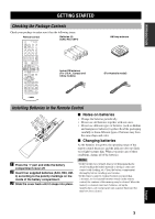
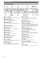
CONTROLS AND FUNCTIONS Front Panel Display 12 3 4 5 678 9 V AUX DSP EX PCM VCR2/DVR VCR 1 CBL/SAT D TV/LD DVD MD/TAPE CD R ES DISCRETE MATRIX VIRTUAL DIGITAL SILENT PRO LOGIC / SP AB DTS Neo:6 DOLBY DIGITAL PRO LOGIC MOVIE TV THEATER 12 ENTERTAINMENT TUNER CD STEREO AUTO TUNED MEMORY PHONO MUTE SLEEP BASS P. DIRECT ft mS dB VOLUME LFE L CR RL RC RR 0 qwe r ty u i o pa 1 DSP indicator Lights up when you select a digital sound field program. 2 Decoder indicators When any of the decoders equipped on this unit functions, the indicator lights up. 3 VIRTUAL indicator Lights up when using Virtual CINEMA DSP (see page 32). 4 Input source indicator Shows the current input source with a cursor. 5 AUTO indicator Shows that this unit is in the automatic tuning mode. 6 SLEEP indicator Lights up while the sleep timer is on. 7 MUTE indicator Flashes while the MUTE function is on. 8 BASS indicator Lights up while BASS EXTENSION is on. 9 VOLUME level indicator Indicates the volume level. 0 v indicator Lights up when this unit is reproducing PCM (pulse code modulation) digital audio signals. q SILENT indicator Lights up when headphones are connected with the sound effect (see "SILENT CINEMA DSP" on page 32). w SP A B indicator Lights up according to which set of main speakers is selected. Both indicators light up when both sets of speakers are selected. e Headphones indicator Lights up when headphones are connected. r DSP program indicators The name of the selected DSP program lights up when the ENTERTAINMENT, MOVIE THEATER 1, MOVIE THEATER 2, TV THEATER or V/DTS SURROUND DSP program is selected. t Multi-information display Shows the current DSP program name and other information when adjusting or changing settings. y STEREO indicator Lights up when this unit is receiving a strong signal for an FM stereo broadcast while the "AUTO" indicator is lit. u TUNED indicator Lights up when this unit tunes in to a station. i MEMORY indicator Flashes to show a station can be stored. o P. DIRECT Lights up while PROCESSOR DIRECT is on. p Input channel indicator Indicates the channel components of input signals being received. a LFE indicator Lights up when the input signal contains the LFE signal. 8
-
 1
1 -
2
-
3
-
4
-
5
-
6
-
 7
7 -
 8
8 -
 9
9 -
 10
10 -
 11
11 -
 12
12 -
 13
13 -
 14
14 -
 15
15 -
 16
16 -
 17
17 -
18
-
19
-
20
-
21
-
22
-
23
-
24
-
25
-
26
-
27
-
28
-
29
-
30
-
31
-
32
-
33
-
34
-
35
-
36
-
37
-
38
-
39
-
40
-
41
-
42
-
43
-
44
-
45
-
46
-
47
-
48
-
49
-
50
-
51
-
52
-
53
-
54
-
55
-
56
-
57
-
58
-
59
-
60
-
61
-
62
-
63
-
64
-
65
-
66
-
67
-
68
-
69
-
70
-
71
-
72
-
73
-
74
-
75
-
76
-
77
-
78
-
79
-
80
-
81
-
82
-
83
-
84
-
85
-
86
-
87
-
88
 |
 |