Yamaha HTR-5590 Owner's Manual - Page 18
CONNECTIONS, Before Connecting Components, Connecting Video Components - owners manual
 |
View all Yamaha HTR-5590 manuals
Add to My Manuals
Save this manual to your list of manuals |
Page 18 highlights
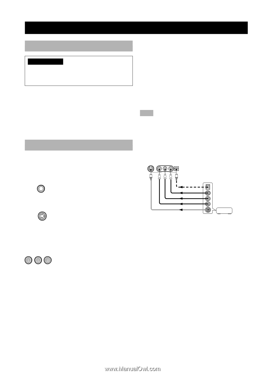
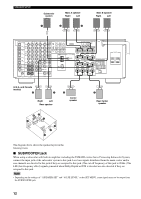
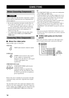
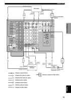
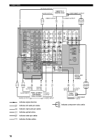
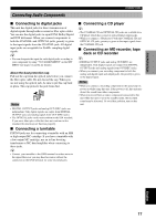
CONNECTIONS Before Connecting Components CAUTION Never connect this unit and other components to mains power until all connections between components have been completed. • Be sure all connections are made correctly, that is to say L (left) to L, R (right) to R, "+" to "+" and "-" to "-". Some components require different connection methods and have different jack names. Refer to the operation instructions for each component to be connected to this unit. • Use commercially available video pin cables when connecting to the S VIDEO and COMPONENT VIDEO jacks. Connecting Video Components I About the video jacks There are three types of video jacks. VIDEO jack VIDEO VIDEO VIDEO jacks transmit composite signals. S VIDEO jack S VIDEO S VIDEO jacks transmit S-video signals. S-video signals are separated into luminance (Y) and color (C) video signals to achieve high-quality color reproduction. COMPONENT VIDEO jacks COMPONENT VIDEO PR/ CR PB/ CB Y COMPONENT VIDEO jacks transmit component signals. Component signals are separated into luminance (Y) and color difference (PB / CB, PR/CR) to provide the best quality in picture reproduction. y • The COMPONENT VIDEO jacks on this unit are independent of the S VIDEO and VIDEO jacks. • Connection depends on the availability of input jacks on your monitor. The signals input through the S VIDEO jacks can be converted to composite signals inside of this unit and output through the VIDEO jacks on this unit as well. • When signals input through both S VIDEO and VIDEO jacks, signals input through the S VIDEO jack has priority. • You can designate the input for the COMPONENT VIDEO A and B jacks according to your component by using "7 I/O ASSIGNMENT" on the SET MENU (see pages 61 and 62 for details). Note • When you are using the COMPONENT VIDEO jacks, check the details in the owner's manual that came with the component being connected. I VIDEO AUX jacks (on the front panel) These jacks are used to connect any video input source such as a game console and a camcorder to this unit. S VIDEO VIDEO L AUDIO R OPTICAL VIDEO AUX S V L R O OPTICAL OUT AUDIO OUT R AUDIO OUT L VIDEO OUT S VIDEO OUT Game console or video camera Refer to the owner's manuals for your monitor and other components being connected to reproduce these signals correctly. You can connect an S-video output and component video output of your video components to this unit. Connect an S-video output to the S VIDEO jack and component video output to the COMPONENT VIDEO jack on this unit. 14
-
 1
1 -
2
-
3
-
4
-
5
-
6
-
7
-
8
-
9
-
10
-
11
-
12
-
 13
13 -
 14
14 -
 15
15 -
 16
16 -
 17
17 -
 18
18 -
 19
19 -
 20
20 -
 21
21 -
 22
22 -
 23
23 -
24
-
25
-
26
-
27
-
28
-
29
-
30
-
31
-
32
-
33
-
34
-
35
-
36
-
37
-
38
-
39
-
40
-
41
-
42
-
43
-
44
-
45
-
46
-
47
-
48
-
49
-
50
-
51
-
52
-
53
-
54
-
55
-
56
-
57
-
58
-
59
-
60
-
61
-
62
-
63
-
64
-
65
-
66
-
67
-
68
-
69
-
70
-
71
-
72
-
73
-
74
-
75
-
76
-
77
-
78
-
79
-
80
-
81
-
82
-
83
-
84
-
85
-
86
-
87
-
88
 |
 |