Yamaha MD8 Owner's Manual - Page 26
Making the Connections GRP & DIR, GRP Method, While pressing the REC SELECT [GROUP] button
 |
View all Yamaha MD8 manuals
Add to My Manuals
Save this manual to your list of manuals |
Page 26 highlights
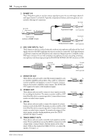
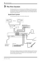
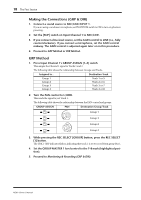
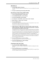
18 The First Session Making the Connections (GRP & DIR) 1. Connect a sound source to MIC/LINE INPUT 1. If you are using a condenser microphone, set PHANTOM switch to ON to turn on phantom powering. 2. Set the [FLIP] switch on Input Channel 1 to MIC/LINE. 3. If you connect a line-level source, set the GAIN control to LINE (i.e., fully counterclockwise). If you connect a microphone, set the GAIN control midway. The GAIN control is adjusted again later on in this procedure. 4. Proceed to GRP Method or DIR Method. GRP Method 1. Press Input Channel 1's GROUP ASSIGN [1-2] switch. This assigns the Channel 1 signal to Tracks 1 and 2. The following table shows the relationship between Groups and Tracks. Assigned to... Destination Track Group 1 Group 2 Group 3 Group 4 → Track 1 or 5 → Track 2 or 6 → Track 3 or 7 → Track 4 or 8 2. Turn the PAN control to L/ODD. This sends the signal to just Track 1. The following table shows the relationship between the PAN control and groups. GROUP ASSIGN PAN Destination Group/Track 1 2 Group 1 3 4 1 2 L ODD R EVEN Group 3 Group 2 3 4 L ODD R EVEN Group 4 3. While pressing the REC SELECT [GROUP] button, press the REC SELECT [1] button. The TRK 1 GRP indicator flashes, indicating that track 1 is set to record from group Bus 1. 4. Set the GROUP MASTER 1 level control to the 7-8 mark (highlighted position). 5. Proceed to Monitoring & Recording (GRP & DIR). MD8-Owner's Manual
-
 1
1 -
2
-
3
-
4
-
5
-
6
-
7
-
8
-
9
-
10
-
11
-
12
-
13
-
14
-
15
-
16
-
17
-
18
-
19
-
20
-
 21
21 -
 22
22 -
 23
23 -
 24
24 -
 25
25 -
 26
26 -
 27
27 -
 28
28 -
 29
29 -
 30
30 -
 31
31 -
32
-
33
-
34
-
35
-
36
-
37
-
38
-
39
-
40
-
41
-
42
-
43
-
44
-
45
-
46
-
47
-
48
-
49
-
50
-
51
-
52
-
53
-
54
-
55
-
56
-
57
-
58
-
59
-
60
-
61
-
62
-
63
-
64
-
65
-
66
-
67
-
68
-
69
-
70
-
71
-
72
-
73
-
74
-
75
-
76
-
77
-
78
-
79
-
80
-
81
-
82
-
83
-
84
-
85
-
86
-
87
-
88
-
89
-
90
-
91
-
92
-
93
-
94
-
95
-
96
-
97
-
98
-
99
-
100
-
101
-
102
-
103
-
104
-
105
-
106
-
107
-
108
-
109
-
110
-
111
-
112
-
113
-
114
-
115
 |
 |
