Yamaha MG20XU Owner's Manual - Page 17
PAD] switch, HPF] High Pass Filter switch, GAIN] knobs, COMP] knobs
 |
View all Yamaha MG20XU manuals
Add to My Manuals
Save this manual to your list of manuals |
Page 17 highlights
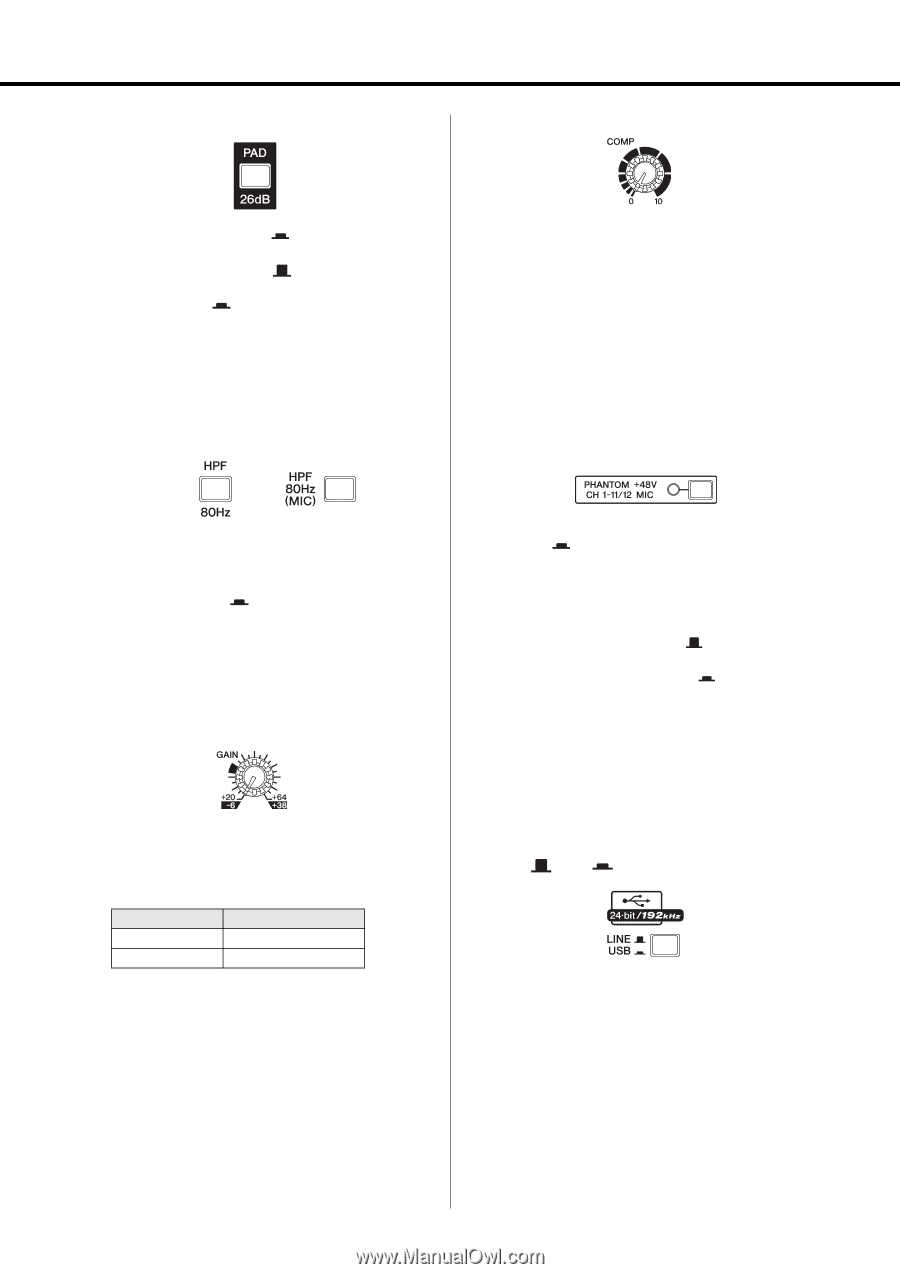
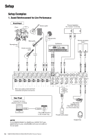
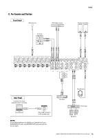
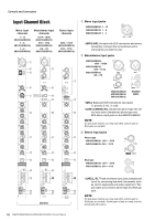
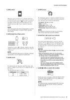
r [PAD] switch u [COMP] knobs Controls and Connectors When this switch is turned on ( ), the input signal from the [MIC/LINE] jack of the mono input channel is attenuated by 26 dB. Turn this switch off ( ) if you've connected a microphone or other device with a low input level to the channel. Turn it on ( ) if you've connected a line-level device. NOTE There may be some noise when operating switches. To prevent this, turn the [ON] switch of a channel off before operating other switches. t [HPF] (High Pass Filter) switch For adjusting the amount of compression applied to the channel. As the [COMP] knob is turned to the right the threshold, ratio, and output gain are adjusted simultaneously. • Threshold: +22 dBu to -8 dBu • Ratio: 1:1 to 4 :1 • Output gain: 0 dB to +7 dB • Attack time: Approximately 25 ms • Release time: Approximately 300 ms NOTE Avoid setting the compression too high; since the resulting higher average output level may lead to feedback. i [PHANTOM +48V] switch and indicator MG20XU/MG20: 1 - 12 MG16XU/MG16: 1 - 8 MG12XU/MG12: 1 - 4 13/14 - 19/20 9/10 - 11/12 5/6 - 7/8 Turning this switch on ( ) will apply a high-pass filter that attenuates frequencies below 80 Hz in the signal by a slope of 12 dB/octave. NOTE Turning the [HPF 80Hz (MIC)] switch on will apply a dedicated high-pass filter only to the signal from the [MIC] jacks. y [GAIN] knobs For adjusting the gain of the input signal. Mono input channels have a [PAD] switch r that lets you change the range of this control. The adjustable gain range is as follows. [PAD] switch ON OFF Range -6 dB to +38 dB +20 dB to +64 dB This switch toggles phantom power on and off. Turn this switch on ( ) to supply DC+48 V to the XLR input jacks. The indicator lights when this switch is on. Turn this switch on when using one or more phantom-powered condenser microphones. NOTICE • Be sure to leave this switch off ( phantom power. ) if you do not need • When turning phantom power on ( ), pay careful attention to the following to prevent damage or noise in the mixing console or connected equipment. - Turn this switch off if equipment that does not use phantom power is connected to the XLR input jacks. - Do not disconnect XLR connector cables while this switch is on. - Set output controls such as the [STEREO] master fader and the [GROUP] fader to their minimum levels before turning phantom power on or off. o [LINE /USB ] switch (XU models) Switches the audio source input on CH19/20 USB IN {CH15/ 16 USB IN} {CH11/12USB IN} between the [LINE] stereo input jack and the [USB 2.0] jack. NOTE The volume input from computers through [USB 2.0] jack can be adjusted by Attenuator Function. Please see Attenuator Function (page 28). MG20XU/MG20/MG16XU/MG16/MG12XU/MG12 Owner's Manual 17
-
 1
1 -
2
-
3
-
4
-
5
-
6
-
7
-
8
-
9
-
10
-
11
-
 12
12 -
 13
13 -
 14
14 -
 15
15 -
 16
16 -
 17
17 -
 18
18 -
 19
19 -
 20
20 -
 21
21 -
 22
22 -
23
-
24
-
25
-
26
-
27
-
28
-
29
-
30
-
31
-
32
-
33
-
34
-
35
-
36
-
37
-
38
-
39
-
40
 |
 |