Yamaha MW12CX Owners Manual - Page 19
STEREO OUT Master Fader, 2TR IN/USB
 |
View all Yamaha MW12CX manuals
Add to My Manuals
Save this manual to your list of manuals |
Page 19 highlights
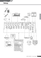
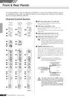
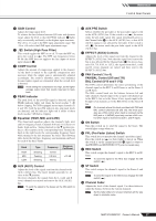
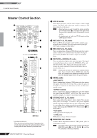
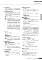
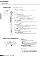
Reference Front & Rear Panels 8 PHONES Jack Connect a pair of headphones to this TRS phone jack. The PHONES jack outputs the same signal as the MONITOR OUT jacks. 9 PHANTOM +48 V Switch This switch toggles phantom power on and off. When the switch is on the mixer supplies +48V phantom power to all channels that have XLR mic input jacks (CHs 1-4, 5/6, 7/8). Turn this switch on when using one or more phantom-powered condenser microphones. NOTE When this switch is on the mixer supplies DC +48 V power to pins 2 and 3 of all XLR-type MIC INPUT jacks. • Be sure to leave this switch off ( ) if you do not need phantom power. CAUTION • When turning the switch on ( ), be sure that only condenser mics are connected to the XLR input jacks (CHs: 1 to 7/8). Devices other than condenser mics may be damaged if connected to the phantom power supply. Note, however, that the switch may be left on when connecting to balanced dynamic microphones. • To avoid damage to speakers, be sure to turn off amplifiers (or powered speakers) before turning this switch on or off. We also recommend that you turn all output controls (STEREO OUT Master Fader, REC OUT Fader, etc.) to their minimum settings before operating the switch to avoid the risk of loud noises that could cause hearing loss or device damage. 0 RETURN • AUX (AUX1) Control Adjusts the level at which the L/R signal received at the RETURN jacks (L (MONO) and R) is sent to the AUX (AUX2) bus. • STEREO Control Adjusts the level at which the signal received at the RETURN jacks (L (MONO) and R) is sent to the STEREO L/R bus. NOTE If you supply a signal to the RETURN L (MONO) jack only, the mixer sends the same signal to both the L and R Stereo buses. A Master SEND • Master AUX (AUX1) Control Adjusts the signal level sent to the AUX (AUX1) SEND jack. • Master EFFECT (AUX2) Control Adjusts the level of the signal sent to the EFFECT (AUX2) bus. NOTE If you are using the MW12CX, the Master EFFECT control does not affect the level of the signal sent from the EFFECT bus to the internal digital effect processor. B POWER Indicator This indicator lights when the mixer's power is ON. C Level Meter This LED meter displays the level of the signal selected by the MONITOR switch D, 2TR IN/USB switch E and PFL switch. The "0" segment corresponds to the nominal output level. The PEAK segment lights red when the output reaches the clipping level. D MONITOR/PHONES • MONITOR Switch If this switch is set to REC ( ), the REC L/R bus signals are sent to the MONITOR OUT jacks, the PHONES jack, and the level meter. If it is set to STEREO ( ), the STEREO L/R bus signals are sent to these jacks and the level meter. • MONITOR Control Controls the level of the signal output to the MONITOR OUT jacks. • PHONES Control Controls the level of the signal output to the PHONES jack. E 2TR IN/USB • 2TR IN/USB Switch If this switch is set to TO MONITOR ( ), the signals input via the 2TR IN jacks and the USB connector are sent to the MONITOR OUT jacks, the PHONES jack, and the level meter. If it is set to TO STEREO ( ), the signals are sent to the STEREO L/R bus. • 2TR IN/USB control Adjusts the level of the signal sent from the 2TR IN jacks and the USB connector to the STEREO L/R bus. The following illustration shows how the switch settings correspond to the signal selection. PFL ON OFF Switches MONITOR/ PHONES 2TR IN/USB - - TO STEREO STEREO TO MONITOR REC TO STEREO TO MONITOR Signals output via the MONITOR/PHONES jacks PFL STEREO (+ 2TR IN/USB) STEREO + 2TR IN/USB * REC REC (+ 2TR IN/USB) * : When overdubbing, you can adjust the levels of the mon- itor playback signal and the signal being recorded separately. For MONI- TOR MIX turn on the REC and ST switches of the corresponding channels. MONITOR MIX Signal Flow 2TR IN/ USB Playback signal STEREO bus Recording signal REC bus 2TR IN/USB control ST switch MONITOR/ PHONES controls MONITOR OUT/PHONES jacks REC switch STEREO OUT Master fader REC OUT fader REC OUT/USB NOTE If the input channel PFL switch is on ( ), then only the PFL output from that channel is sent to the C-R OUT jacks, PHONES jacks, and level meter. F REC OUT Fader Adjusts the signal level sent to the REC OUT jacks and the USB connector. G ST Switch If this switch is on ( ), the signals are sent to the STEREO L/R bus via the REC OUT fader F. The REC L signal goes to Stereo L and the REC R signal goes to Stereo R. H STEREO OUT Master Fader Adjusts the signal level sent to the STEREO OUT jacks. MW12CX/MW12C Owner's Manual 19
-
 1
1 -
2
-
3
-
4
-
5
-
6
-
7
-
8
-
9
-
10
-
11
-
12
-
13
-
 14
14 -
 15
15 -
 16
16 -
 17
17 -
 18
18 -
 19
19 -
 20
20 -
 21
21 -
 22
22 -
 23
23 -
 24
24 -
25
-
26
-
27
-
28
-
29
-
30
-
31
-
32
-
33
-
34
 |
 |