Yamaha N12 Owners Manual - Page 18
Control Room CONTROL ROOM LEVEL] control - support
 |
UPC - 086792859866
View all Yamaha N12 manuals
Add to My Manuals
Save this manual to your list of manuals |
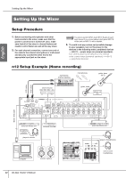
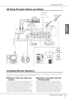
Page 18 highlights
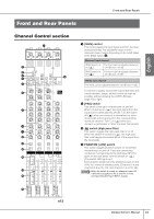
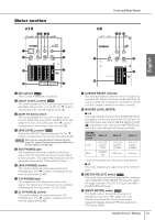
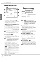
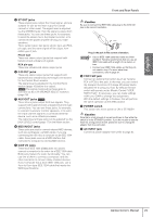
Front and Rear Panels Control Room section n12 n8 1 2 3 3 4 7 4 6 6 5 8 5 English 1 C-R SPEAKER SELECT switches Only These switches select the jacks that will output the control room monitor signal. When you turn on one of the switches, the LED lights up, and the corresponding jacks output the monitoring signal. Switch Output jacks C-R SPEAKER SELECT [A] switch C-R OUT jacks A (L/R) C-R SPEAKER SELECT [B] switch C-R OUT jacks B (L/R) C-R SPEAKER SELECT [C] switch C-R OUT jacks C (L/R) NOTE While the C-R SOURCE SELECT (3) [5.1] switch is turned on, you can use these switches to individually turn the surround channels on and off. For more information, please refer to page 47. 2 [DOWN MIX] switch Only This switch converts 5.1-ch surround signals (input from the DAW) into 2-ch L/R signals. While the switch is on, converted 2-ch signals are output from the C-R OUT jacks A. NOTE • In order to monitor in a surround environment, you will need a surround-capable application such as Cubase 4. The included Cubase AI 4 does not support surround. • This switch is effective only while the C-R SOURCE SELECT [5.1] switch is turned on. 3 C-R SOURCE SELECT switches These switches enable you to select a monitoring source (the signal output from the C-R OUT jacks). The following switches and monitoring sources are available: [5.1] switch Enables you to monitor the 5.1-ch surround Only signal input from the DAW. (page 46) [DAW] switch Enables you to monitor the DAW stereo signal (DAW IN 1/2). [ST] switch Enables you to monitor the STEREO bus signal. [AUX] switch Enables you to monitor the AUX bus signal. [2TR] switch Enables you to monitor only the input signal at the 2TR IN jacks. 18 Owner's Manual NOTE • Only In order to monitor in a surround environment, you will need Cubase 4. The included Cubase AI 4 does not support surround. • You can turn on the [5.1] switch and [ST] switch simultaneously. In this case, the 5.1-ch L/R signal and STEREO bus L/R channel signals will be mixed and output. 4 [DIMMER] switch This switch turns on and off the Dimmer function that temporarily lowers the monitoring volume. For example, this can be convenient when you want to have a conversation in the control room. 5 [MUTE] switch This switch turns on and off the Mute function that mutes the monitoring signal. Repeatedly pressing the switch toggles between on (the switch will light up) and off (the switch will turn off). 6 [CONTROL ROOM LEVEL] control This control adjusts the monitoring volume in the control room. Turning the knob clockwise will increase the volume level. 7 TALKBACK [LEVEL] control Only This control adjusts the input level of the built-in microphone. The "▼" position corresponds to the nominal level (0 dB). 8 [TALKBACK] switch Only This switch turns on and off the Talkback function, which enables you to communicate with the musicians. When the Talkback function is turned on, the switch LED will flash and the Dimmer function (4) will be enabled. NOTE The talkback signal will be sent to the AUX outputs (AUX PHONES jack and AUX OUT jacks).
-
 1
1 -
2
-
3
-
4
-
5
-
6
-
7
-
8
-
9
-
10
-
11
-
12
-
 13
13 -
 14
14 -
 15
15 -
 16
16 -
 17
17 -
 18
18 -
 19
19 -
 20
20 -
 21
21 -
 22
22 -
 23
23 -
24
-
25
-
26
-
27
-
28
-
29
-
30
-
31
-
32
-
33
-
34
-
35
-
36
-
37
-
38
-
39
-
40
-
41
-
42
-
43
-
44
-
45
-
46
-
47
-
48
-
49
-
50
-
51
-
52
-
53
-
54
-
55
-
56
-
57
-
58
-
59
-
60
-
61
-
62
 |
 |
