Yamaha YHT-S401 Owners Manual - Page 7
Controls and functions, Front panel of the subwoofer integrated receiver
 |
View all Yamaha YHT-S401 manuals
Add to My Manuals
Save this manual to your list of manuals |
Page 7 highlights
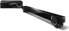
INTRODUCTION Controls and functions ■ Front panel of the subwoofer integrated receiver Getting started 1 2 3 4 5 67 8 1 STATUS indicator Lights up to show the system condition. (☞ P. 10) 4 USB port For connecting a USB device. (☞ P. 16) 2 (Power) Turns on the unit, or sets it to standby mode. (☞ P. 10) Note 5 VOLUME -/+ Controls the volume of the unit. (☞ P. 10) 6 PHONES jack For connecting headphones. (☞ P. 10) A small amount of electricity is consumed to receive the infrared signal from the remote control even when the unit is in standby mode. 3 INPUT Selects an input source you want to listen to. (☞ P. 10) 7 Remote control sensor Receives infrared signals from the remote control. (☞ P. 2, 5) 8 Front panel display Shows information about the operational status of the unit. (☞ P. 4) ■ Rear panel of the subwoofer integrated receiver 7 6 5 43 1 1 Power Cable For connecting an AC wall outlet. (☞ P. 8) 2 HDMI IN 1 - 3/HDMI OUT (ARC) jack • HDMI IN 1 - 3 for connecting HDMI compatible external components. (☞ P. 9) • HDMI OUT for connecting an HDMI compatible TV. (☞ P. 9) 3 DIGITAL IN (TV) jack For connecting optical digital cable to the TV. (☞ P. 9) 2 4 DIGITAL IN (STB) jack For connecting digital audio pin cable to the STB. (☞ P. 9) 5 ANALOG INPUT jack For connecting analog audio cable to external components. (☞ P. 9) 6 ANTENNA terminal For connecting supplied FM antenna. (☞ P. 9) 7 SPEAKERS terminal For connecting speakers. (☞ P. 8) 3 En English
-
 1
1 -
 2
2 -
 3
3 -
 4
4 -
 5
5 -
 6
6 -
 7
7 -
 8
8 -
 9
9 -
 10
10 -
 11
11 -
 12
12 -
13
-
14
-
15
-
16
-
17
-
18
-
19
-
20
-
21
-
22
-
23
-
24
-
25
-
26
-
27
-
28
-
29
-
30
-
31
-
32
-
33
-
34
-
35
-
36
-
37
-
38
-
39
-
40
 |
 |
