Yamaha YV-1600A Owner's Manual - Page 27
is flush with the upper leg flange. Refer to step
 |
View all Yamaha YV-1600A manuals
Add to My Manuals
Save this manual to your list of manuals |
Page 27 highlights
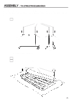
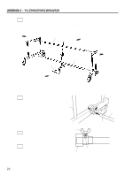
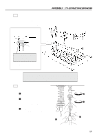
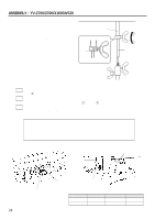
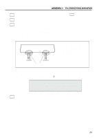
ASSEMBLY : YV-2700/2700G/1600A/520 13 Adjust the pedal stroke. (Refer to YV-3910/3710/3700 assembly step 10-1 on page 17.) 14 After assembly, confirm that each bolt and screw is tightened securely. 15 Height adjustment should always be performed by at least 2 persons. To adjust the height of the tone bars, first remove the round belt (fan belt), driver, controller and tone bars*, and loosen the center rod fixing bolts. (* To remove the tone bars, disengage the springs on the low sound side, and then unhook the string from the post.) Support both frame ends by hand (do not touch the metal parts shown in the illustration), and loosen the slide leg fixing bolts. Frame For height adjustment, make sure to support the instrument by the wooden frame. Do not touch the metal parts. Do not touch ! Lift the frame ends to the desired height and then securely tighten each slide leg fixing bolt, aligning it with the corresponding notch of the slide leg. Bolt and notch are aligned when the next higher notch is flush with the upper leg flange. (Refer to step , on page 23.) When a slide leg fixing bolt is tightened in between two notches, there is a danger of the slide leg slipping. Always make sure that the slide legs are held securely. 16 This completes the assembly of the instrument. To play, connect the supplied AC adapter to the DC 12V IN jack of the controller. (Refer to YV-3700 assembly procedure, "Power Supply", on page 19.) 25
-
 1
1 -
2
-
3
-
4
-
5
-
6
-
7
-
8
-
9
-
10
-
11
-
12
-
13
-
14
-
15
-
16
-
17
-
18
-
19
-
20
-
21
-
 22
22 -
 23
23 -
 24
24 -
 25
25 -
 26
26 -
 27
27 -
 28
28
 |
 |