Zanussi ZHC9244X User Manual - Page 65
Installation
 |
View all Zanussi ZHC9244X manuals
Add to My Manuals
Save this manual to your list of manuals |
Page 65 highlights
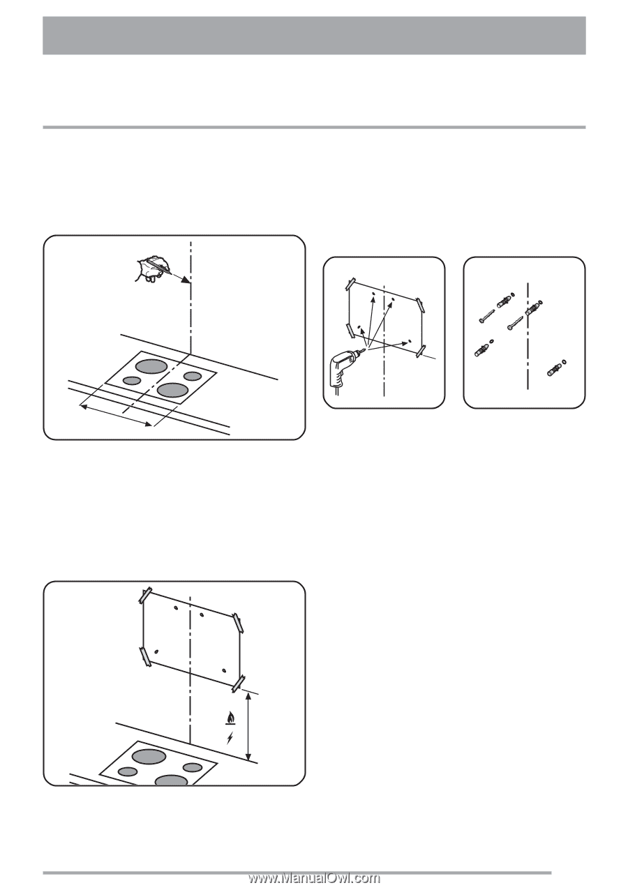
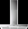
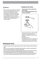
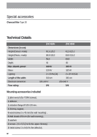
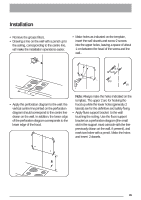
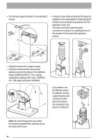
Installation • Remove the grease filters. • Drawing a line on the wall with a pencil up to the ceiling, corresponding to the centre line, will make the installation operations easier. • Make holes as indicated on the template, insert the wall dowels and screw 2 screws into the upper holes, leaving a space of about 1 cm between the head of the screw and the wall.. Ø 8 5x45 Ø 8 Ø 8 = = • Apply the perforation diagram to the wall: the vertical centre line printed on the perforation diagram should correspond to the centre line drawn on the wall. In addition, the lower edge of the perforation diagram corresponds to the lower edge of the hood. Note: Always make the holes indicated on the template. The upper 2 are for hooking the hood up while the lower holes (generally 2 lateral) are for the definitive and safety fixing. • Apply flues support bracket to the wall touching the ceiling. Use the flues support bracket as a perforation diagram (the small slot in the support must coincide with the line previously drawn on the wall, if present), and mark two holes with a pencil. Make the holes and insert 2 dowels. 65
-
 1
1 -
2
-
3
-
4
-
5
-
6
-
7
-
8
-
9
-
10
-
11
-
12
-
13
-
14
-
15
-
16
-
17
-
18
-
19
-
20
-
21
-
22
-
23
-
24
-
25
-
26
-
27
-
28
-
29
-
30
-
31
-
32
-
33
-
34
-
35
-
36
-
37
-
38
-
39
-
40
-
41
-
42
-
43
-
44
-
45
-
46
-
47
-
48
-
49
-
50
-
51
-
52
-
53
-
54
-
55
-
56
-
57
-
58
-
59
-
 60
60 -
 61
61 -
 62
62 -
 63
63 -
 64
64 -
 65
65 -
 66
66 -
 67
67 -
 68
68 -
 69
69 -
 70
70 -
71
-
72
-
73
-
74
-
75
-
76
-
77
-
78
-
79
-
80
-
81
-
82
-
83
-
84
 |
 |