ASRock ALiveNF4G-DVI Quick Installation Guide - Page 19
HDMI_SPDIF connector of HDMI
 |
View all ASRock ALiveNF4G-DVI manuals
Add to My Manuals
Save this manual to your list of manuals |
Page 19 highlights
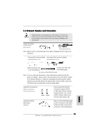
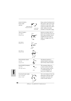
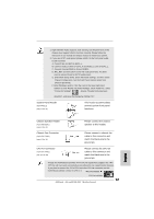
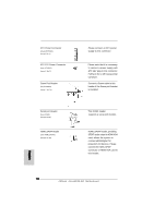
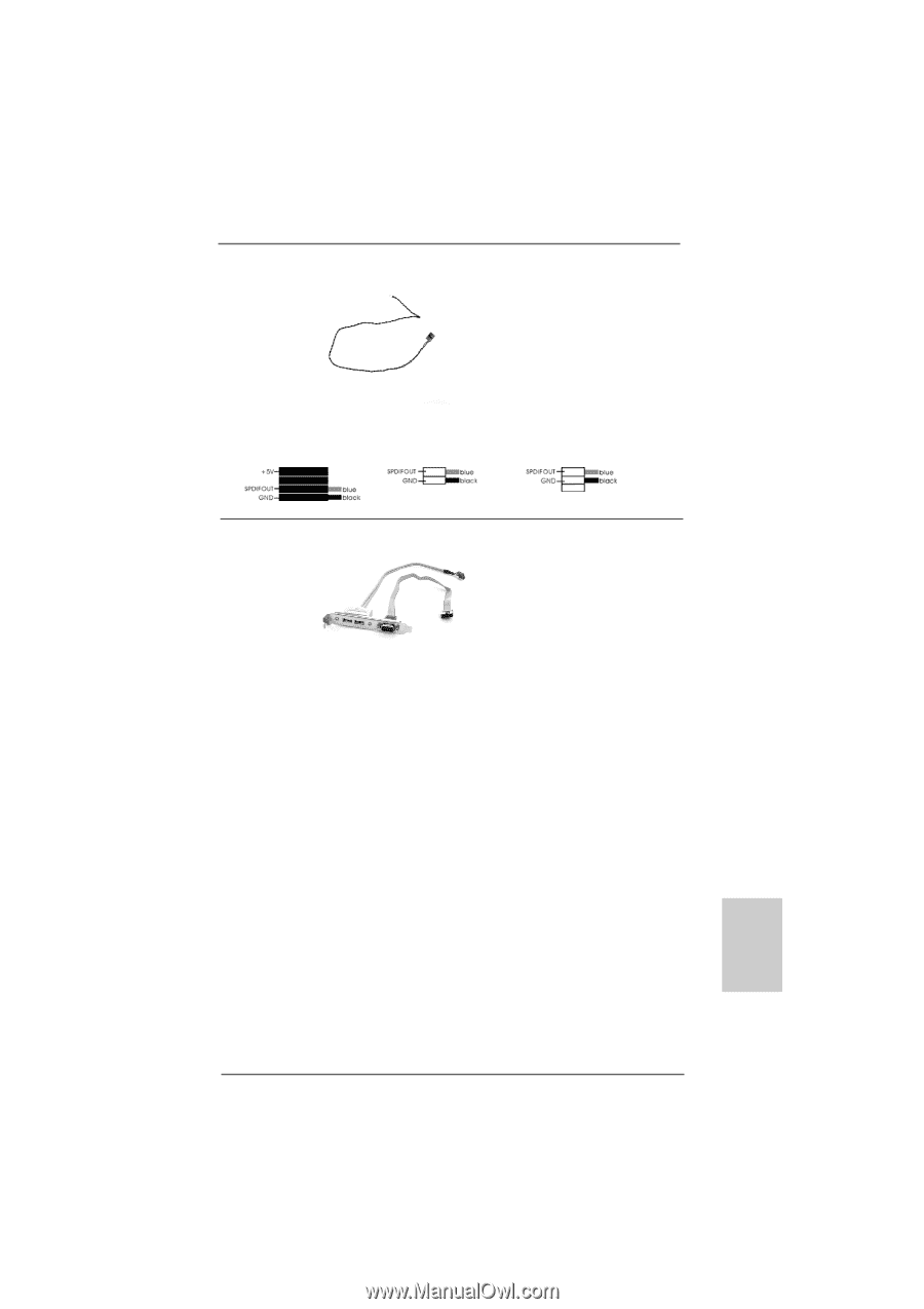
HDMI_SPDIF Cable (Optional) A. black end C B A Please connect the black end (A) of HDMI_SPDIF cable to the HDMI_SPDIF header on the motherboard. Then connect the white end (B or C) of HDMI_SPDIF cable to the HDMI_SPDIF connector of HDMI VGA card. B. white end (2-pin) C. white end (3-pin) USB+COM Port Bracket (Optional) This USB+COM port bracket can support 2 additional USB 2.0 ports and 1 COM port. Please connect the blue connector on the cable of this USB+COM port bracket to the USB 2.0 header (USB2_3, USB4_5, or USB6_7), and connect the black connector on the cable of this USB+COM port bracket to the serial port header (COM1). Then fasten the USB+COM port bracket to the chassis with screws. English 19 ASRock ALiveNF4G-DVI Motherboard
-
 1
1 -
2
-
3
-
4
-
5
-
6
-
7
-
8
-
9
-
10
-
11
-
12
-
13
-
 14
14 -
 15
15 -
 16
16 -
 17
17 -
 18
18 -
 19
19 -
 20
20 -
 21
21 -
 22
22 -
 23
23 -
 24
24 -
25
-
26
-
27
-
28
-
29
-
30
-
31
-
32
-
33
-
34
-
35
-
36
-
37
-
38
-
39
-
40
-
41
-
42
-
43
-
44
-
45
-
46
-
47
-
48
-
49
-
50
-
51
-
52
-
53
-
54
-
55
-
56
-
57
-
58
-
59
-
60
-
61
-
62
-
63
-
64
-
65
-
66
-
67
-
68
-
69
-
70
-
71
-
72
-
73
-
74
-
75
-
76
-
77
-
78
-
79
-
80
-
81
-
82
-
83
-
84
-
85
-
86
-
87
-
88
-
89
-
90
-
91
-
92
-
93
-
94
-
95
-
96
-
97
-
98
-
99
-
100
-
101
-
102
-
103
-
104
-
105
-
106
-
107
-
108
-
109
-
110
-
111
-
112
-
113
-
114
-
115
-
116
-
117
-
118
-
119
-
120
-
121
-
122
-
123
-
124
-
125
-
126
-
127
-
128
-
129
-
130
-
131
-
132
-
133
-
134
-
135
-
136
-
137
-
138
-
139
-
140
-
141
-
142
-
143
-
144
-
145
-
146
-
147
-
148
-
149
-
150
-
151
-
152
-
153
-
154
-
155
-
156
-
157
-
158
-
159
-
160
-
161
-
162
-
163
-
164
 |
 |
19
19
19
19
19
ASRock
ALiveNF4G-DVI
Motherboard
English
English
English
English
English
C
B
A
HDMI_SPDIF Cable
Please connect the black end (A)
(Optional)
of HDMI_SPDIF cable to the
HDMI_SPDIF header on the
motherboard. Then connect the
white end (B or C) of
HDMI_SPDIF cable to the
HDMI_SPDIF connector of HDMI
VGA card.
A. black end
B. white end (2-pin)
C. white end (3-pin)
USB+COM Port Bracket
This USB+COM port bracket can
(Optional)
support 2 additional USB 2.0
ports and 1 COM port.
Please connect the blue connec-
tor on the cable of this USB+COM
port bracket to the USB 2.0
header (USB2_3, USB4_5, or
USB6_7), and connect the black
connector on the cable of this
USB+COM port bracket to the
serial port header (COM1). Then
fasten the USB+COM port
bracket to the chassis with
screws.