ASRock M266A R3.0 User Manual
ASRock M266A R3.0 Manual
 |
View all ASRock M266A R3.0 manuals
Add to My Manuals
Save this manual to your list of manuals |
ASRock M266A R3.0 manual content summary:
- ASRock M266A R3.0 | User Manual - Page 1
M266A User Manual Version 3.0 Published July 2003 Copyright©2003 ASRock INC. All rights reserved. 1 - ASRock M266A R3.0 | User Manual - Page 2
any form or by any means, except duplication of documentation by the purchaser for backup purpose, without written consent of ASRock Inc. Products and corporate names appearing in this manual may or may not be registered trademarks or copyrights of their respective companies, and are used only for - ASRock M266A R3.0 | User Manual - Page 3
Jumpers Setup 12 2.8 Connectors 13 3 BIOS Setup 15 3.1 BIOS Setup Utility 15 3.2 BIOS Setup Utility Main Menu 15 3.3 Legend Support 27 4.1 Installing Operating System 27 4.2 Support CD Information 27 4.2.1 Running The Support CD 27 4.2.2 Drivers Menu 27 4.2.3 Utilities Menu 27 4.2.4 ASRock - ASRock M266A R3.0 | User Manual - Page 4
with robust design conforming to ASRock's commitment to quality and endurance. Chapter 1 and 2 of this manual contain introduction of the motherboard and step-bystep installation guide for new DIY system builders. Chapter 3 and 4 contain basic BIOS setup and Support CD information. Because the - ASRock M266A R3.0 | User Manual - Page 5
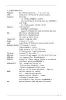
for two additional ASRock I/OTM: USB 2.0 ports upgrade (see CAUTION 2) PS/2: 1 keyboard port / 1 mouse port; 1 RJ 45 port; 4 rear default USB 2.0 ports; 1 VGA port;1 parallel port: ECP/EPP support; Audio Jack: Line Out / Line In / Microphone + 1 Game port BIOS: AMI BIOS; Supports "Plug and - ASRock M266A R3.0 | User Manual - Page 6
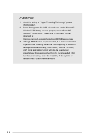
to Microsoft® official document at http://www.microsoft.com/whdc/hwdev/bus/USB/USB2support.mspx 3. Although M266A offers stepless control, it is not recommended to perform over clocking. When the CPU frequency of M266A is set to perform over clocking, other clocks, such as PCI clock, AGP clock, and - ASRock M266A R3.0 | User Manual - Page 7
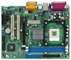
LAN (optional) USB 2.0 Ports USB 2.0 Ports Line out LAN PHY LiLInnineein CD1 MMIniicc in AUX1 JL1 JR1 2MB BIOS 1 AUDIO1 AUDIO CODEC VIA P4M266A Chipset M266A AGP1 PCI 1 IDE1 Super I/O PCI 2 COM1 IR1 1 1 PS2_USB_PWR1 1 AMR1 CMOS Battery CLRCMOS1 FLOPPY1 USB45 1 20 19 1817 - ASRock M266A R3.0 | User Manual - Page 8
1.4 ASRock I/OTM 1 Parallel Port 3 Game Port 5 Line In (Light Blue) 7 USB 2.0 Ports 9 PS/2 Keyboard Port (Purple) 2 RJ-45 Port 4 Microphone (Pink) 6 Line Out (Lime) 8 VGA Port 10 PS/2 Mouse Port (Green) 8 - ASRock M266A R3.0 | User Manual - Page 9
Chapter 2 Installation M266A is a Micro ATX form factor (9.6" x 7.5", 24.4 x 19.1 cm) motherboard. directly on the carpet or the like. Also remember to use a grounded wrist strap or touch a safety grounded object before you handle components. 3. Hold components by the edges and do not touch the - ASRock M266A R3.0 | User Manual - Page 10
sure that the CPU and the heatsink are securely fastened and in good contact with each other. For proper installation, please kindly refer to the instruction manuals of vendors of CPU fan and heatsink. 10 - ASRock M266A R3.0 | User Manual - Page 11
AGP Slots) There are 2 PCI slots, 1 AMR slot, and 1 AGP slot on M266A motherboard. PCI slots: PCI slots are used to install expansion cards that have the 32-bit slot: The AGP slot is used to install a graphics card. The ASRock AGP slot has a special locking mechanism which can securely fasten the - ASRock M266A R3.0 | User Manual - Page 12
work. 2. If both jumper caps on JL1 and JR1 are removed (see fig. 2), only front panel audio works. However, it requires your front panel to support the function. CLRCMOS1 (see p.7 item 15) Clear CMOS 2-pin jumper Note: CLRCMOS1 allows you to clear the data in CMOS. The data in CMOS includes - ASRock M266A R3.0 | User Manual - Page 13
the secondary IDE connector (IDE2, black). USB 2.0 header (9-pin USB45) (see p.7 item 16) ASRock I/OTM provides you 4 default USB 2.0 ports on the rear panel. If the rear USB ports IR1) (see p.7 item 17) This connector supports an optional wireless transmitting and receiving infrared module. 13 - ASRock M266A R3.0 | User Manual - Page 14
black wire to the ground pin. Connect an ATX power supply to the connector. Serial port connector (9-pin COM1) (see p.7 item 20) This COM1 header supports a serial port module. 14 - ASRock M266A R3.0 | User Manual - Page 15
the reset button on the system chassis. You can also restart by turning the system off and then back on. Because the BIOS software is constantly being updated, the following BIOS setup screens and descriptions are for refer ence purpose only, and may not exactly match what you see on your screen - ASRock M266A R3.0 | User Manual - Page 16
Time Floppy Drives IDE Devices Jul 08 2003 Tue 20:07:40 Month: Jan - Dec Day: 01 - 31 Year: 1980 - 2099 BIOS Version Processor Type Processor Speed Cache Size Microcode Update Total Memory DDR1 DDR2 M266 BIOS P1.50 Pentium (R) 4 CPU 2400 MHz 512 KB F24 / 0F 224 MB + 32 MB Share Memory - ASRock M266A R3.0 | User Manual - Page 17
size for the hard disk drive that you configured. [USER]: It allows user to manually enter the number of cylinders, heads, and sectors per track for the drive. , the BIOS Setup may detect incorrect parameters. In these cases, select [User] to manually enter the IDE hard disk drive parameters. 17 - ASRock M266A R3.0 | User Manual - Page 18
per track. Refer to the drive documentation to determine the correct value. Maximum Capacity This field shows the drive's maximum capacity as calculated by the BIOS based on the drive information you entered. LBA Mode This allows user to select the LBA mode for a hard disk > 512 MB under DOS and - ASRock M266A R3.0 | User Manual - Page 19
options: [Setup], [Always]. If [Setup] option is selected, the "Password Check" is performed before BIOS setup. If [Always] option is selected, the "Password Check" is performed before both boot-up and BIOS setup. Boot From Network Use this to enable or disable "boot from network" feature. Boot - ASRock M266A R3.0 | User Manual - Page 20
Transaction Hyper-Threading Technology USB Controller USB Device Legacy Support Disabled Auto 133MHz Locked Auto 4x 128MB 32MB 2.5 Manual] This allows user to set CPU host frequency manually. However, this is not recommended unless user thoroughly knows the feature. Wrong setup may cause problems - ASRock M266A R3.0 | User Manual - Page 21
are not PCI 2.1 compliant. Hyper-Threading Technology To enable this feature, it requires a computer system with an Intel Pentium® 4 processor that supports Hyper-Threading technology and an operating system that includes optimization for this technology, such as Microsoft® Windows® XP SP1. Set to - ASRock M266A R3.0 | User Manual - Page 22
allows you to select whether to auto-detect or disable the ACPI Suspend-to-RAM feature. Select [Auto] will enable this feature if the system supports it. Repost Video on STR Resume This feature allows you to repost video on STR resume. Restore on AC/Power Loss This allows you to - ASRock M266A R3.0 | User Manual - Page 23
3.8 PCI / Plug and Play Setup AMIBIOS SETUP UTILITY - VERSION 3.31a PCI / Plug and Play Setup [ Setup Help ] PCI Latency Timer (PCI Clocks) 32 Primary Graphics Adapter PCI to select PCI clocks. Leave on default setting for the best PCI performance. F1:Help Esc:Previous Menu :Select - ASRock M266A R3.0 | User Manual - Page 24
3.9 Peripheral Setup AMIBIOS SETUP UTILITY - VERSION 3.31a Peripheral Configuration [ Setup Help ] OnBoard FDC OnBoard Serial Port OnBoard Infrared Port OnBoard Parallel Port Parallel Port Mode EPP Version Parallel Port IRQ Parallel Port DMA Channel OnBoard Midi Port Midi IRQ Select OnBoard Game - ASRock M266A R3.0 | User Manual - Page 25
OnBoard IDE You may enable either the primary IDE channel or the secondary IDE channel. Or you may enable both the primary and the secondary IDE channels by selecting [Both]. Set to [Disabled] will disable the both. Configuration options: [Disabled], [Primary], [Secondary], [Both]. OnBoard LAN This - ASRock M266A R3.0 | User Manual - Page 26
box that lets you install optimized defaults for all appropriate items in the BIOS Setup Utility. Press to install the default values. The optimized if you install the optimized defaults when your hardware does not support them. 3.13 Save Settings and Exit Select this item and press - ASRock M266A R3.0 | User Manual - Page 27
detects installed devices. Install the necessary drivers to activate the devices. 4.2.3 Utilities Menu The Utilities Menu shows the applications software that the motherboard supports. Click on a specific item then follow the installation wizard to install it. 4.2.4 ASRock PC-DIY Live Demo Program
-
 1
1 -
 2
2 -
 3
3 -
 4
4 -
 5
5 -
 6
6 -
 7
7 -
8
-
9
-
10
-
11
-
12
-
13
-
14
-
15
-
16
-
17
-
18
-
19
-
20
-
21
-
22
-
23
-
24
-
25
-
26
-
27
 |
 |

1
M266A
User Manual
Version 3.0
Published July 2003
Copyright©2003 ASRock INC. All rights reserved.