ASRock M266A R3.0 User Manual - Page 12
Jumpers Setup
 |
View all ASRock M266A R3.0 manuals
Add to My Manuals
Save this manual to your list of manuals |
Page 12 highlights
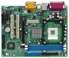
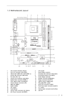
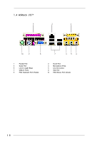
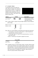
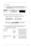
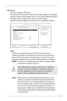
2.7 Jumpers Setup The illustration shows how jumpers are setup. When the jumper cap is placed on pins, the jumper is "SHORT". If no jumper cap is placed on pins, the jumper is "OPEN". The illustration shows a 3-pin jumper whose pin1 and pin2 are "SHORT" when jumper cap is placed on these 2 pins. Jumper Setting Description PS2_USB_PWR1 1_2 2_3 Short pin2, pin3 to enable (see p.7 item 18) +5V +5VSB +5VSB (standby) for PS/2 or USB wake up events. Note: To select +5VSB, it requires 2 Amp and higher standby current provided by power supply. JR1(see p.7 item 23) JL1(see p.7 item 24) JL1 JR1 fig. 1 JL1 JR1 fig. 2 Note: When you connect speakers in back panel and front panel at the same time, 1. If the jumpers JL1 and JR1 are short (see fig. 1), both front panel and rear panel audio connectors can work. 2. If both jumper caps on JL1 and JR1 are removed (see fig. 2), only front panel audio works. However, it requires your front panel to support the function. CLRCMOS1 (see p.7 item 15) Clear CMOS 2-pin jumper Note: CLRCMOS1 allows you to clear the data in CMOS. The data in CMOS includes system setup information such as system password, date, time, and system setup parameters. To clear and reset the system parameters to default setup, please turn off the computer and unplug the power cord, then use a jumper cap to short the pins on CLRCMOS1 for 3 seconds. Please remember to remove the jumper cap after clearing the CMOS. 12
-
 1
1 -
2
-
3
-
4
-
5
-
6
-
 7
7 -
 8
8 -
 9
9 -
 10
10 -
 11
11 -
 12
12 -
 13
13 -
 14
14 -
 15
15 -
 16
16 -
 17
17 -
18
-
19
-
20
-
21
-
22
-
23
-
24
-
25
-
26
-
27
 |
 |