Asus K7M K7M User Manual
Asus K7M - Motherboard - ATX Manual
 |
View all Asus K7M manuals
Add to My Manuals
Save this manual to your list of manuals |
Asus K7M manual content summary:
- Asus K7M | K7M User Manual - Page 1
R K7M Slot A Motherboard USER'S MANUAL - Asus K7M | K7M User Manual - Page 2
manual revision number. Manual updates are represented by the third digit in the manual revision number. For previous or updated manuals, BIOS, drivers, or product release information, contact ASUS at http://www.asus.com.tw or through any of the means indicated on the following page. SPECIFICATIONS - Asus K7M | K7M User Manual - Page 3
@asuscom.de (for marketing requests only) Technical Support Hotline: MB/Others: +49-2102-9599-0 Notebook: +49-2102-9599-10 Fax: +49-2102-9599-11 Support (Email): www.asuscom.de/de/support (for online support) WWW: www.asuscom.de FTP: ftp.asuscom.de/pub/ASUSCOM ASUS K7M User's Manual 3 - Asus K7M | K7M User Manual - Page 4
3.7.2 Assigning IRQs for Expansion Cards 31 3.7.3 Assigning DMA Channels for ISA Cards 32 3.7.4 ISA Cards and Hardware Monitor 33 3.7.5 Accelerated Graphics Port 33 3.7.6 Audio Modem Riser (AMR) Slot 33 3.8 External Connectors 34 3.9 Power Connection Procedures 45 4 ASUS K7M User's Manual - Asus K7M | K7M User Manual - Page 5
46 4.1.2 Updating BIOS Procedures 48 4.2. BIOS Setup Program 49 4.2.1 BIOS Menu Bar Windows 98 First Time Installation 71 5.2 K7M Support CD 72 5.3 Audio Driver (only with onboard audio option 73 5.4 PC-cillin 98 74 5.5 Acrobat Reader Vx.x 75 5.6 IDE Driver 76 5.7 Miniport Driver 77 5.8 ASUS - Asus K7M | K7M User Manual - Page 6
and used in accordance with manufacturer's instructions, may cause harmful interference to radio communications Part 15 of the FCC Rules. Reprinted from the Code of Federal Regulations #47, part 15.193, 1993. radio noise emissions from digital apparatus set out in the Radio Interference Regulations - Asus K7M | K7M User Manual - Page 7
1.2.1 Motherboard (1) ASUS Motherboard (1) Universal Retention Mechanism (factory installed) (1) ASUS USB Connector Set (1) Ribbon cable for master and slave UltraDMA/33 & UltraDMA/66 IDE drives (1) Ribbon cable for (1) 3.5" floppy disk drive (1) Bag of spare jumper caps (1) Support CD with drivers - Asus K7M | K7M User Manual - Page 8
The ASUS K7M Motherboard The ASUS K7M motherboard is carefully designed for the demanding PC user who wants high-performance features in a small package. 2.1.1 Specifications • AMD Athlon™ Processor Support: Supports AMD Athlon™ processor designed for the AMD Athlon™ Processor Module (242-pin Slot - Asus K7M | K7M User Manual - Page 9
and manage system status information, such as CPU and system voltages, temperatures, and fan status through the onboard hardware ASIC and the bundled ASUS PC Probe. • Additional USB Ports: For more peripheral connectivity, two additional USB ports are supported midboard. ASUS K7M User's Manual 9 - Asus K7M | K7M User Manual - Page 10
for systems and components are based on the following high-level goals: Support for Plug and Play compatibility and power management for configuring and managing all system components, and 32-bit device drivers and installation procedures for Windows 95/98/NT. 10 ASUS K7M User's Manual - Asus K7M | K7M User Manual - Page 11
for RPM and failure. All the fans are set for its normal RPM range and alarm thresholds. • Voltage Monitoring and Alert: Processor and system voltage levels are monitored to ensure stable current to critical motherboard components. Voltage specifications are more critical for future processors, so - Asus K7M | K7M User Manual - Page 12
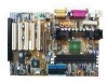
2. FEATURES Motherboard Parts 2. FEATURES 2.2 Motherboard Parts See opposite page for locations. 1 Slot A 2 AMD North Bridge (AGP/PCI/Memory Controller) 3 ATX Power Connector 4 DIMM Sockets 5 IDE Connectors 6 Floppy Disk Drive Connector 7 USB Connector (Port 2 & Port 3) (optional) 8 - Asus K7M | K7M User Manual - Page 13
2. FEATURES Motherboard Parts 2. FEATURES 2.2 Motherboard Parts...continued 1 23 4 5 6 23 22 21 20 19 18 17 16 15 14 13 12 11 10 9 8 7 ISA model. ISA slots are optional at the time of purchase. Models without ISA will have 5 PCI slots. ASUS K7M User's Manual 13 - Asus K7M | K7M User Manual - Page 14
FLOPPY Mic In CD CPU Core Voltage Setting (VID) Audio Modem Riser (AMR) MODEM TRCPU Row 5 4 3 2 1 0 DSW1 DIP Switches TRPWR Accelerated Graphic Port (AGP) VIDEO AUX Audio Codec Audio Codec Setting (SPK, AUD_EN1, AUD_EN2, ADN#) HPHONE PCI Slot 1 PCI Slot 2 K7M PS/2 Mouse VIA Selection - Asus K7M | K7M User Manual - Page 15
Setting Expansion Slots 1) DIMM1, DIMM2, DIMM3 p.22 168-Pin DIMM Memory Support 2) Slot A p.25 Central Processing Unit (CPU) 3) ISA1, ISA2 p.31 16-bit ISA Bus Expansion Slots (optional) 4) PCI1, PCI2, PCI3, PCI4, PCI5 p.31 32-bit PCI Bus Expansion Slots 5) AGP p.33 Accelerated Graphics Port - Asus K7M | K7M User Manual - Page 16
(PANEL) 25) SMI (PANEL) p.44 System Warning Speaker Connector (4 pins) p.44 System Power LED Lead (3-1 pins) p.44 Reset Switch Lead (2 pins) p.44 ATX Power / Soft-Off Switch Lead (2 pins) p.44 System Management Interrupt Switch Lead (2 pins) 3. H/W SETUP Layout Contents 16 ASUS K7M User's Manual - Asus K7M | K7M User Manual - Page 17
• Install Memory Modules • Install the Central Processing Unit (CPU) • Install Expansion Cards • Connect Ribbon Cables, Panel Wires, and Power Supply 3.4 Motherboard Settings This section explains in detail how to change your motherboard's function settings through the use of switches and/or jumpers - Asus K7M | K7M User Manual - Page 18
add-in cards if you are not using a PS/2 mouse. Set to IRQ12 if you do not have a PS/2 mouse. Set to MSDATA if you want to use a PS/2 mouse. MSDATA K7M 123 123 IRQ12 (w/o PS/2 Mouse) MSDATA (w/ PS/2 Mouse) K7M PS/2 Mouse Selection 3. H/W SETUP Motherboard Settings 18 ASUS K7M User's Manual - Asus K7M | K7M User Manual - Page 19
must also be disabled. Setting Enable AUDIO CODEC [1-2] [1-2] [1-2] [1-2] Disable [2-3] [2-3] [2-3] [2-3] Enable Onboard Audio Codec Disable Onboard Audio Codec SPK AUD_EN2 SPK AUD_EN2 3 3 K7M 2 2 1 1 AUD_EN1 ADN# AUD_EN1 ADN# K7M Audio Codec Setting ASUS K7M User's Manual 19 - Asus K7M | K7M User Manual - Page 20
12 ON 12 103MHz 110MHz NOTE: Frequency Multiple settings are not available here because AMD Athlon™ processors have locked Frequency Multiples. NOTE: The motherboard supports PC100 (100MHz)/PC133 (133MHz) DIMMs for system memory. 3. H/W SETUP Motherboard Settings 20 ASUS K7M User's Manual - Asus K7M | K7M User Manual - Page 21
jumpers allow you to manually adjust the CPU core voltage. It is recommended to use CPU Default as the CPU core voltage. CPU Default means the Vcore is generated according to the CPU VID configuration. For each jumper setting, there are two voltage options, depending on the CPU used. K7M K7M CPU - Asus K7M | K7M User Manual - Page 22
involved under this speed. • This motherboard supports SPD (Serial Presence Detect) DIMMs. This is the memory of choice for best performance vs BIOS shows SDRAM memory on bootup screen. • Single-sided DIMMs come in 16, 32, 64,128MB; double-sided come in 32, 64, 128, 256MB. 22 ASUS K7M User's Manual - Asus K7M | K7M User Manual - Page 23
will shift between left, center, or right to identify the type and also to prevent the wrong type from being inserted into the DIMM slot on the motherboard. You must ask your retailer the correct DIMM type before purchasing. This motherboard supports four clock signals. ASUS K7M User's Manual 23 - Asus K7M | K7M User Manual - Page 24
3. HARDWARE SETUP (This page was intentionally left blank.) 3. H/W SETUP 24 ASUS K7M User's Manual - Asus K7M | K7M User Manual - Page 25
. Your motherboard provides a Slot A connector for an AMD Athlon™ processor. 3. H/W SETUP CPU AMD Athlon™ processor with heatsink and fan (top view) 3.6.1 Universal Retention Mechanism Your motherboard comes preinstalled with a Universal Retention Mechanism (URM). The URM supports the AMD Athlon - Asus K7M | K7M User Manual - Page 26
to release. Lock Arm Lock Arm WARNING! Make sure the heatsink is mounted tightly against the cartridge; otherwise, the CPU will overheat. Make sure you install an auxiliary fan to provide adequate circulation across the processor's passive heatsink. 3. H/W SETUP CPU 26 ASUS K7M User's Manual - Asus K7M | K7M User Manual - Page 27
cartridge in place by pushing the cartridge until it is firmly seated on the Slot A connector. The SECC locks should be outward when secured so that the lock shows through the retention mechanism's lock holes. Lock hole CPU fan cable to fan connector 3. H/W SETUP CPU ASUS K7M User's Manual 27 - Asus K7M | K7M User Manual - Page 28
to Slot A CPU thermal problems are available from ASUSTeK COMPUTER INC.: the ASUS Smart Fan or ASUS S-K7FAN and the ASUS P2TCable. ASUS S-K7FAN The optional ASUS Smart Fan or ASUS S-K7FAN is a CPU fan the boxed processor heatsink with fan, as indicated. Tab Sensor 28 ASUS K7M User's Manual - Asus K7M | K7M User Manual - Page 29
Slot A Processors The recommended heatsinks for the Slot A processors are those with three-pin fans, such as the ASUS Smart Fan, that can be connected to the motherboard's CPU Client Manager (LDCM) or the ASUS PC Probe software. 3. H/W SETUP CPU SECC Heatsink & Fan ASUS K7M User's Manual 29 - Asus K7M | K7M User Manual - Page 30
3. HARDWARE SETUP (This page was intentionally left blank.) 3. H/W SETUP 30 ASUS K7M User's Manual - Asus K7M | K7M User Manual - Page 31
INT-D - - - shared - - shared - If using PCI cards on shared slots, make sure that the drivers support "Share IRQ" or that the cards do not need IRQ assignments. Conflicts will arise between the two PCI groups that will make the system unstable or cards inoperable. ASUS K7M User's Manual 31 - Asus K7M | K7M User Manual - Page 32
you configure the card's jumpers manually and then install it in an available slot on the ISA bus. To see a map of your used and free IRQs in Windows 98, the Control Panel icon in My Computer, contains a System icon, which gives you a Device Manager tab. Doubleclicking on a specific hardware device - Asus K7M | K7M User Manual - Page 33
Graphics Port This motherboard provides an accelerated graphics port (AGP) slot to support a new generation of graphics cards with ultra-high memory bandwidth, such as an ASUS 3D Hardware Accelerator. K7M K7M Accelerated Graphics Port (AGP) 3.7.6 Audio Modem Riser (AMR) Slot This connector supports - Asus K7M | K7M User Manual - Page 34
from jumpers in the Motherboard Layout. Placing jumper caps over these connector pins will cause damage to your motherboard. IMPORTANT PS/2 mouse if one is detected. If one is not detected, expansion cards can use IRQ12. See PS/2 Mouse Function Control in 4.4 Advanced Menu. 34 ASUS K7M User's Manual - Asus K7M | K7M User Manual - Page 35
second serial port is available using a serial port bracket connected from the motherboard to an expansion slot opening. See Onboard Serial Port 1 in 4.2.2 I/O Device Configuration for settings. 3. H/W SETUP D CMoAnCnhecatnonrsels COM 1 COM 2 Serial Ports (9-pin Male) ASUS K7M User's Manual 35 - Asus K7M | K7M User Manual - Page 36
In (light blue) allows tape players or other audio sources to be recorded by your computer or played through the Line Out (lime). Mic (pink) allows microphones to be connected for inputting voice. Line Out Line In Mic 1/8" Stereo Audio Connectors 3. H/W SETUP Connectors 36 ASUS K7M User's Manual - Asus K7M | K7M User Manual - Page 37
setting its jumper accordingly. Please refer to your hard disk documentation for the jumper settings. BIOS now supports specific and another on a SCSI drive and select the boot disk through 4.4.1 Advanced CMOS Setup. IMPORTANT: K7M PIN 1 K7M Floppy Disk Drive Connector ASUS K7M User's Manual 37 - Asus K7M | K7M User Manual - Page 38
COM port. IMPORTANT: This feature requires that Wake-On-Ring features are enabled (see 4.4.3 Power Management) and that your system has an ATX power supply with at least 720mA +5V standby power. 3. H/W SETUP Connectors WOR K7M 1 2 Ground Ring# K7M Wake-On-Ring Connector 38 ASUS K7M User - Asus K7M | K7M User Manual - Page 39
motherboard and/or the CPU fan if these pins are incorrectly used. These are not jumpers, do not place jumper caps over these pins. Power Supply Fan GND +12V Rotation CPU Fan Power Rotation +12V GND K7M Chassis Fan Power K7M 12-Volt Cooling Fan Power GND +12V Rotation ASUS K7M User's Manual - Asus K7M | K7M User Manual - Page 40
True-Level Line Out Header (3 pin HPHONE) This connector allows you to connect a chassis mounted headphone to the motherboard instead of having to attach an external headphone onto the ATX connectors. HP OUT LT GND HP OUT RT K7M K7M True-Level Line Out Header 1 HPHONE 40 ASUS K7M User's Manual - Asus K7M | K7M User Manual - Page 41
an SMBus host and/or other SMBus devices. SMBus is a specific implementation of an I2C bus, which is a multi-device bus; that is, multiple chips can be connected to the same bus and each one can act as a master by initiating data transfer. K7M K7M SMBus Connector 1 SMB ASUS K7M User's Manual 41 - Asus K7M | K7M User Manual - Page 42
to the chassis panel or on any should open and the motherboard will record a chassis lead is not used, a jumper cap must be placed over the -LAN support, your ATX power K7M -5.0 Volts Power Good +5.0 Volts +5V Standby +5.0 Volts +12.0Volts K7M ATX Power Connector 42 ASUS K7M User's Manual - Asus K7M | K7M User Manual - Page 43
-1 pin USBPORT) If the USB Ports on the back panels are inadequate, a USB connector set is available midboard. If you want to use this connector, you need to use the bundled external connector set. The external connector set connects to the 10-1 pin block and mounts to an open slot on your computer - Asus K7M | K7M User Manual - Page 44
will not cause any problems. This may require one or two presses depending on the position of the switch. Wake-up can be controlled by settings in the BIOS but the keyboard will always allow wake-up (the SMI lead cannot wake up the system). 3. H/W SETUP Connectors 44 ASUS K7M User's Manual - Asus K7M | K7M User Manual - Page 45
power, the system may have failed a power-on test. Recheck your jumper settings and connections or call your retailer for assistance. 7. During power-on, hold down to enter BIOS Setup. Follow the instructions in 4. BIOS SETUP. * Powering Off your computer: You must first exit or shut down - Asus K7M | K7M User Manual - Page 46
. It will not work with DOS prompt in Windows and will not work with certain memory drivers that may be loaded when you boot from your hard drive. It is recommended that you reboot using a floppy disk. 3. Reboot your computer from the floppy disk. NOTE: BIOS Setup must specify "Floppy" as the first - Asus K7M | K7M User Manual - Page 47
Use the up or down keypad arrow to select the BIOS Filename for saving field. Type a filename and the path, for example, A:\XXXXXXXX.XXX and then press . 7. When the saving is finished, "BIOS ROM data saving successful." will be displayed. 4. BIOS SETUP Updating BIOS K7M User's Manual 47 - Asus K7M | K7M User Manual - Page 48
if the problem still persists, update the original BIOS file you saved to disk above. If the Flash EPROM Programming Utility was not able to successfully update a complete BIOS file, your system may not be able to boot up. If this happens, your system will need servicing. 48 ASUS K7M User's Manual - Asus K7M | K7M User Manual - Page 49
make your selections among the predetermined choices. NOTE: Because the BIOS software is constantly being updated, the following BIOS screens and descriptions are for reference purposes only and may not reflect your BIOS screens exactly. 4. BIOS SETUP Program Information ASUS K7M User's Manual 49 - Asus K7M | K7M User Manual - Page 50
the left or right Loads the Setup default values Loads the last set values Save changes and exit Setup Scroll Bar When a scroll bar appears to window. Use the up and down arrow keys to scroll through the entire menu. 4. BIOS SETUP Menu Introduction 50 ASUS K7M User's Manual - Asus K7M | K7M User Manual - Page 51
appear in the item specific Setup Help window located to the right of each menu. This window displays the help text for the currently selected field. NOTE: SETUP defaults are noted in square brackets next to each function heading. 4. BIOS SETUP Menu Introduction ASUS K7M User's Manual 51 - Asus K7M | K7M User Manual - Page 52
(01 to 31), Year: (1901 to 2099) SystemTime To set the time, select this field and then press or to set the current time fields is that this option allows the BIOS program to remember the drive information and to manually enter the information for those devices. 52 ASUS K7M User's Manual - Asus K7M | K7M User Manual - Page 53
main menu and press . The default setting [Auto] leads you to a screen as follows: Under the [Auto] setting, the BIOS is able to detect the drive type manufacturer of the drive. Incorrect settings may cause your system to not recognize the installed hard disk. ASUS K7M User's Manual 53 - Asus K7M | K7M User Manual - Page 54
motherboard supports the 32 bit transfer mode. Leave on default setting. Boot Sector Virus Protection [Disabled] This field allows you to set boot virus detection, ensuring a virus-free boot is set to [Disabled] to prevent write errors. 4. BIOS SETUP Master/Slave Drives 54 ASUS K7M User's Manual - Asus K7M | K7M User Manual - Page 55
this window: Advanced CMOS Setup, Advanced Chipset Setup, Power Management Setup, Plug and Play Setup, Peripheral Setup, and Hardware Monitor Setup. Use the ↑ or ↓ keypad arrow to select the Setup menu you want to configure and then press . 4. BIOS SETUP Advanced Menu ASUS K7M User's Manual - Asus K7M | K7M User Manual - Page 56
Analysis and Reporting Technology) support for S.M.A.R.T.-capable hard disk drives. This technology requires an application that can display S.M.A.R.T. warning messages. Boot Up NumLock [On] This field enables users to activate the Number Lock function upon system boot. 56 ASUS K7M User's Manual - Asus K7M | K7M User Manual - Page 57
If you install other expansion cards with ROMs on them, you will need to know which addresses the ROMs use to shadow them specifically. Shadowing a ROM reduces the memory available between 640KB and 1024KB by the amount used for this purpose. 4. BIOS SETUP Advanced CMOS ASUS K7M User's Manual 57 - Asus K7M | K7M User Manual - Page 58
amount of time in HCLKs that the DRAM controller waits to close a DRAM page after the CPU becomes idle. NOTE: To make changes to this field, the Configure SDRAM Timing by SPD field must be set to [Disabled]. Available options: [1 Cycle] [8 Cycles] [32 Cycles] [64 Cycles] 58 ASUS K7M User's Manual - Asus K7M | K7M User Manual - Page 59
specifically require this setting. Setting the address space to a particular setting will make that memory space unavailable to the system. Expansion cards can only access memory up to 16MB. Available options: [Disabled] [14MB15MB] [15MB-16MB] [14MB-16MB] 4. BIOS SETUP Advanced Chipset ASUS K7M - Asus K7M | K7M User Manual - Page 60
[USB Port 0&1] [USB Port 2&3] [All USB Port] USB KB/Mouse Legacy Support [Disabled] Leave on the default setting [Disabled] if you are not using any USB legacy devices. Available options: [Disabled] [Keyboard] [Keyb+Mouse] Chipset Features 4. BIOS SETUP Advanced Chipset 60 ASUS K7M User's Manual - Asus K7M | K7M User Manual - Page 61
] [Off] Video Power Down Mode [Stand By] (*APM feature) This field determines when to power down the monitor for monitor power management. The monitor automatically wakes up when any specified system activity is detected. Available options: [Disabled] [Stand By] [Suspend] ASUS K7M User's Manual 61 - Asus K7M | K7M User Manual - Page 62
is able to detect the CPU and motherboard temperatures. Set to [Monitor] to use setting, holding the ATX switch for more than 4 seconds will power off the system. NOTE: This field is only effective in APM OS system. Available options: [On/Off] [Suspend] 4. BIOS SETUP 62 ASUS K7M User's Manual - Asus K7M | K7M User Manual - Page 63
signal. With this feature, you can remotely upload/download data to/from systems during off-peak hours. Set to [Enabled] to use this feature. IMPORTANT: This feature requires the ASUS PCI-L101 LAN Card (see APPENDIX) or a similar ethernet card and an ATX power supply with at least 720mA +5V standby - Asus K7M | K7M User Manual - Page 64
configure the PCI bus slots instead of using the BIOS. Thus interrupts may cards, such as graphics accelerators or MPEG Video Cards, may not show colors properly. The setting [Enabled] should correct this problem. Otherwise, leave this on the default setting of [Disabled]. 64 ASUS K7M User's Manual - Asus K7M | K7M User Manual - Page 65
you are not using an ISA Configuration Utility (ICU) to specify its address range, select a memory size from the three available options: [16k], [32k], and [64k]; the Reserved Memory Address field will then be enabled for selecting the base address. 4. BIOS SETUP PCI/PnP ASUS K7M User's Manual 65 - Asus K7M | K7M User Manual - Page 66
while the option [ASK IR] reserves the serial port 2 for Amplitude Shift Keyed (ASK) infrared communications. IR Pins / Duplex Mode / Receiver Polarity / Transmitter Polarity [N/A] These fields are only selectable when Serial Port2 Mode is set to [IrDA] or [ASK IR]. 66 ASUS K7M User's Manual - Asus K7M | K7M User Manual - Page 67
to use a MIDI device onboard. MPU-401 I/O Address [300h-303h] This sets the I/O address for the onboard MIDI device. To access this field, the MPU-401 field must be enabled. Game Port (200h-207h) [Enabled] Enable this field to use the game port. 4. BIOS SETUP Peripheral ASUS K7M User's Manual 67 - Asus K7M | K7M User Manual - Page 68
CPU and MB (motherboard) temperatures. Set to [Ignore] only if necessary. Current CPU Fan / PS Fan / Chassis Fan Speed [xxxxRPM] The onboard hardware monitor is able to detect the CPU voltage regulators. Set to [Ignore] only if necessary. 4. BIOS SETUP Hardware Monitor 68 ASUS K7M User's Manual - Asus K7M | K7M User Manual - Page 69
. To erase the RTC RAM: (1) Unplug your computer, (2) Short the solder points, (3) Turn ON your computer, (4) Hold down during bootup and enter BIOS Setup to re-enter user preferences. 01 01 01 Short solder points to Clear CMOS K7M ® R182 K7M Clear RTC RAM ASUS K7M User's Manual 69 - Asus K7M | K7M User Manual - Page 70
Menu 4. BIOS SETUP Exit Menu Exit Saving Changes Select this option to save into the CMOS memory all modifications you and then press again to confirm your choice. Load Optimal Settings (Setup Defaults) This option allows you to load the optimal value ( RAM. 70 ASUS K7M User's Manual - Asus K7M | K7M User Manual - Page 71
NT 4.0, you must use Service Pack 3.0 or later. 5.1.1 Windows 98 First Time Installation When you start Windows for the first time after the installation of your motherboard, Windows 98 will detect the onboard audio and video chips and may attempt to install a driver from its system registry. When - Asus K7M | K7M User Manual - Page 72
of this motherboard's manual is available in PDF format at any of our web sites. • IDE Driver: Installs VIA Bus Master PCI IDE Controller Driver. • Miniport Driver: Installs the necessary AGP miniport driver for the K7 Series motherboards with AMD-751 chipset under Windows 9x. • ASUS PC Probe - Asus K7M | K7M User Manual - Page 73
manufacturer and insert the Support CD into your CD-ROM drive. 2. Click OK. 3. Click Browse. 4. Locate the D:\Audio\WIN9X folder (where D is your CD-ROM Drive) and click OK. 5. Click OK again and the driver files will be copied. 6. Click Yes to restart the computer. ASUS K7M User's Manual 73 - Asus K7M | K7M User Manual - Page 74
SOFTWARE SETUP 5.4 PC-cillin 98 Insert the Support CD that came with your motherboard into your CD-ROM drive or double-click installation if no viruses are found. Click here to start installation. 5. S/W SETUP Windows 98 (5) Click here. (6) & (7) Select the preferred features by clicking the - Asus K7M | K7M User Manual - Page 75
5. SOFTWARE SETUP 5.5 Acrobat Reader Vx.x Insert the Support CD that came with your motherboard into your CD-ROM drive or double-click the CD drive icon in My the License Agreement. (4) Click here. (5) Click here and then click Finish to restart. 5. S/W SETUP Windows 98 ASUS K7M User's Manual 75 - Asus K7M | K7M User Manual - Page 76
5. SOFTWARE SETUP 5.6 IDE Driver Insert the Support CD that came with your motherboard into your CD-ROM drive or double-click the CD drive icon in My copying files. (2) Click here. (4) Click here. (5) Click here and then click Finish to restart. 5. S/W SETUP Windows 98 76 ASUS K7M User's Manual - Asus K7M | K7M User Manual - Page 77
SETUP 5.7 Miniport Driver Insert the Support CD that came with your motherboard into your CD-ROM drive or double-click the CD drive icon in My Computer to bring up the setup screen. (1) Click here. (2) Click here. (3) Click Finish to restart. 5. S/W SETUP Windows 98 ASUS K7M User's Manual 77 - Asus K7M | K7M User Manual - Page 78
, see 5.12 Uninstalling Programs. (1) Click here. (2) Click here. (3) Click here. (4) Click here. 5. S/W SETUP Windows 98 (5) Click here. (6) Click here. (7) Click here. (8) Click Next and when the Setup Complete box appears, click Finish to complete setup. 78 ASUS K7M User's Manual - Asus K7M | K7M User Manual - Page 79
S-YXG50 (only with onboard audio option) Insert the Support CD that came with your motherboard into your CD-ROM drive serial number can be found on this software's license agreement card. (5) Click Yes to signify your acceptance of the conditions S/W SETUP Windows 98 ASUS K7M User's Manual 79 - Asus K7M | K7M User Manual - Page 80
5. SOFTWARE SETUP 5.10 YAMAHA XGStudio (only with onboard audio) Insert the Support CD that came with your motherboard into your CD-ROM drive or double-click the CD drive icon in copying the necessary files. (6) Click OK to begin using XGStudio. 5. S/W SETUP Windows 98 80 ASUS K7M User's Manual - Asus K7M | K7M User Manual - Page 81
within Windows. You may use this function if a program does not provide its own uninstallation program. 5. S/W SETUP Windows 98 (1) Double-click here to open the Add/Remove Programs Properties dialog box. (2) Select the program to remove and click here. (3) Click here. ASUS K7M User's Manual - Asus K7M | K7M User Manual - Page 82
(This page was intentionally left blank.) 82 ASUS K7M User's Manual - Asus K7M | K7M User Manual - Page 83
. It also has a utility that lets you review useful information about your computer, such as hard disk space, memory usage, and CPU type, CPU speed, and internal/external frequencies through the DMI Explorer. 6.1.1 Starting ASUS PC Probe When ASUS PC Probe starts, a splash screen appears allowing - Asus K7M | K7M User Manual - Page 84
6. SOFTWARE REFERENCE 6.1.2 Using ASUS PC Probe Monitoring Monitor Summary Shows a summary of the items being monitored. Temperature Monitor Shows the PC's temperature the threshold level or down to decrease the threshold level) Voltage Monitor Shows the PC's voltages. 84 ASUS K7M User's Manual - Asus K7M | K7M User Manual - Page 85
6. S/W REFERENCE ASUS PC Probe 6. SOFTWARE REFERENCE Settings Lets you set threshold levels and polling intervals or refresh times of the PC's drives and the file allocation table or file system used. Memory Shows the PC's memory load, memory usage, and paging file usage. ASUS K7M User's Manual 85 - Asus K7M | K7M User Manual - Page 86
a summary of devices in your PC. DMI Explorer Shows information pertinent to the PC, such as CPU type, CPU speed, and internal/external frequencies, and memory size. Utility Lets you run programs outside of the ASUS Probe modules. To run a program, click Execute Program. 86 ASUS K7M User's Manual - Asus K7M | K7M User Manual - Page 87
icon will bring up a menu to open or exit ASUS PC Probe and pause or resume all system monitoring. When the ASUS PC Probe senses a problem with your PC, portions of the ASUS PC Probe icon changes to red, the PC speaker beeps, and the ASUS PC Probe monitor is displayed. ASUS K7M User's Manual 87 - Asus K7M | K7M User Manual - Page 88
6. SOFTWARE REFERENCE (This page was intentionally left blank) 6. S/W REFERENCE 88 ASUS K7M User's Manual - Asus K7M | K7M User Manual - Page 89
taskbar to start YAMAHA XGPlayer. 6.2.1 YAMAHA XGstudio Player Control Panel Closes the player. NOTE: You can also close Designates the start-play location to the beginning of the song. Displays the Set Sound Source dialog box. Displays Help. NOTE: You can also display ASUS K7M User's Manual 89 - Asus K7M | K7M User Manual - Page 90
and memory? • Do you have the required software, such as MS-DOS and Windows? • Were you able to install using the specified procedure? No sound • Is the MIDI driver correctly installed? • Is the tone generator set correctly? • Is volume set to zero in the XGstudio Player or XGstudio Mixer panels - Asus K7M | K7M User Manual - Page 91
Panel Panel Image Switcher Smart Arranger Song Stop Voice Select Slider Function Assign Slider Master Volume Slider Channel Solo Channel Realtime Mute Slider Select Previous Play Pause Select Next Image Switcher (AVI file): Video in the drum channel (10ch). ASUS K7M User's Manual 91 - Asus K7M | K7M User Manual - Page 92
switch between seven ensemble voice sets with these buttons. To return to the original voice set, click . Piano Orchestra Mallet Techno Choir Robot Nature Return 6.3.2 About the video display screen If an AVI : The BMP file should not exceed 320 x 240 pixels. 92 ASUS K7M User's Manual - Asus K7M | K7M User Manual - Page 93
motherboard, set the jumper to "Other." Connect the Wake on LAN (WOL) output signal to the motherboard's WOL_CON to utilize the Wake-On-LAN feature of the motherboard. Connect the LAN activity output signal (LAN_LED) to the system cabinet's front panel LAN_LED to display LAN data activity. ASUS K7M - Asus K7M | K7M User Manual - Page 94
7. APPENDIX ASUS LAN Card 7. APPENDIX 7.1.1 Features • Intel 82558 Ethernet LAN Controller (Fully integrated 10BASE-T/100BASE-TX) • Wake-On-LAN Remote Control Function Supported • PCI Bus Master Complies with PCI Local Bus Rev. 2.1 specifications • Consists of MAC & PHY (10/100Mbps) interfaces • - Asus K7M | K7M User Manual - Page 95
(This page was intentionally left blank.) ASUS K7M User's Manual 95 - Asus K7M | K7M User Manual - Page 96
(This page was intentionally left blank.) 96 ASUS K7M User's Manual
-
 1
1 -
 2
2 -
 3
3 -
 4
4 -
 5
5 -
 6
6 -
 7
7 -
8
-
9
-
10
-
11
-
12
-
13
-
14
-
15
-
16
-
17
-
18
-
19
-
20
-
21
-
22
-
23
-
24
-
25
-
26
-
27
-
28
-
29
-
30
-
31
-
32
-
33
-
34
-
35
-
36
-
37
-
38
-
39
-
40
-
41
-
42
-
43
-
44
-
45
-
46
-
47
-
48
-
49
-
50
-
51
-
52
-
53
-
54
-
55
-
56
-
57
-
58
-
59
-
60
-
61
-
62
-
63
-
64
-
65
-
66
-
67
-
68
-
69
-
70
-
71
-
72
-
73
-
74
-
75
-
76
-
77
-
78
-
79
-
80
-
81
-
82
-
83
-
84
-
85
-
86
-
87
-
88
-
89
-
90
-
91
-
92
-
93
-
94
-
95
-
96
 |
 |

R
K7M
Slot A Motherboard
USER’S MANUAL