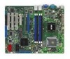
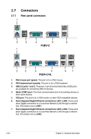
Asus P5BV-C User Guide - Page 43
Internal connectors
 |
UPC - 610839157372
View all Asus P5BV-C manuals
Add to My Manuals
Save this manual to your list of manuals |
Page 43 highlights
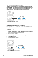
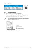
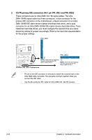
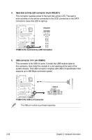
LAN port LED indications ACT/LINK LED SPEED LED Status Description Status Description OFF GREEN BLINKING No link Linked Data activity OFF YELLOW GREEN No link 100 Mbps connection 1 Gbps connection ACT/LINK SPEED LED LED LAN port 2.7.2 Internal connectors 1. Floppy disk drive connector (34-1 pin FLOPPY1) This connector is for the provided Floppy Disk Drive (FDD) signal cable. Insert one end of the cable to this connector, then connect the other end to the signal connector at the back of the floppy disk drive. Pin 5 on the connector is removed to prevent incorrect cable connection when using an FDD cable with a covered Pin 5. ® P5BV-C/4L FLOPPY PIN1 NOTE: Orient the red markings on the floppy ribbon cable to PIN 1. P5BV-C/4L Floppy Disk Drive Connector ASUS P5BV-C Series 2-23
-
 1
1 -
2
-
3
-
4
-
5
-
6
-
7
-
8
-
9
-
10
-
11
-
12
-
13
-
14
-
15
-
16
-
17
-
18
-
19
-
20
-
21
-
22
-
23
-
24
-
25
-
26
-
27
-
28
-
29
-
30
-
31
-
32
-
33
-
34
-
35
-
36
-
37
-
 38
38 -
 39
39 -
 40
40 -
 41
41 -
 42
42 -
 43
43 -
 44
44 -
 45
45 -
 46
46 -
 47
47 -
 48
48 -
49
-
50
-
51
-
52
-
53
-
54
-
55
-
56
-
57
-
58
-
59
-
60
-
61
-
62
-
63
-
64
-
65
-
66
-
67
-
68
-
69
-
70
-
71
-
72
-
73
-
74
-
75
-
76
-
77
-
78
-
79
-
80
-
81
-
82
-
83
-
84
-
85
-
86
-
87
-
88
-
89
-
90
-
91
-
92
-
93
-
94
-
95
-
96
-
97
-
98
-
99
-
100
-
101
-
102
-
103
-
104
-
105
-
106
-
107
-
108
-
109
-
110
-
111
-
112
-
113
-
114
-
115
-
116
-
117
-
118
-
119
-
120
-
121
-
122
-
123
-
124
-
125
-
126
-
127
-
128
-
129
-
130
-
131
-
132
-
133
-
134
-
135
-
136
-
137
-
138
-
139
-
140
-
141
-
142
-
143
-
144
-
145
-
146
-
147
-
148
-
149
-
150
-
151
-
152
-
153
-
154
-
155
-
156
-
157
-
158
-
159
-
160
-
161
 |
 |
