Asus P5BV-C User Guide - Page 49
Chassis, and power fan connectors 4-pin FRNT_FAN1, FRNT_FAN2, FRNT_FAN3, REAR_FAN1 and CPU_FAN1
 |
UPC - 610839157372
View all Asus P5BV-C manuals
Add to My Manuals
Save this manual to your list of manuals |
Page 49 highlights
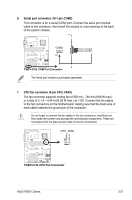
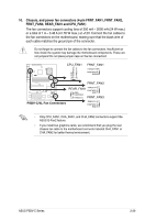
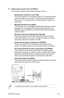
10. Chassis, and power fan connectors (4-pin FRNT_FAN1, FRNT_FAN2, FRNT_FAN3, REAR_FAN1 and CPU_FAN1) The fan connectors support cooling fans of 350 mA ~ 2000 mA (24 W max.) or a total of 1 A ~ 3.48 A (41.76 W max.) at +12V. Connect the fan cables to the fan connectors on the motherboard, making sure that the black wire of each cable matches the ground pin of the connector. Do not forget to connect the fan cables to the fan connectors. Insufficient air flow inside the system may damage the motherboard components. These are not jumpers! Do not place jumper caps on the fan connectors! CPU_FAN1 FRNT_FAN1 FANOUT4 FANPWR2 GND ® GND FANPWR2 FANOUT4 P5BV-C/4L P5BV-C/4L Fan Connectors FRNT_FAN2 REAR_FAN1 FANOUT4 FANPWR2 GND GND FANPWR2 FANOUT4 FRNT_FAN3 FANOUT4 FANPWR2 GND • Only CPU_FAN1, CHA_FAN1, and CHA_FAN2 connectors support the ASUS Q-Fan2 feature. • If you install two graphics cards, we recommend that you plug the rear chassis fan cable to the motherboard connector labeled CHA_FAN1 or CHA_FAN2 for better thermal environment. ASUS P5BV-C Series 2-29
-
 1
1 -
2
-
3
-
4
-
5
-
6
-
7
-
8
-
9
-
10
-
11
-
12
-
13
-
14
-
15
-
16
-
17
-
18
-
19
-
20
-
21
-
22
-
23
-
24
-
25
-
26
-
27
-
28
-
29
-
30
-
31
-
32
-
33
-
34
-
35
-
36
-
37
-
38
-
39
-
40
-
41
-
42
-
43
-
 44
44 -
 45
45 -
 46
46 -
 47
47 -
 48
48 -
 49
49 -
 50
50 -
 51
51 -
 52
52 -
 53
53 -
 54
54 -
55
-
56
-
57
-
58
-
59
-
60
-
61
-
62
-
63
-
64
-
65
-
66
-
67
-
68
-
69
-
70
-
71
-
72
-
73
-
74
-
75
-
76
-
77
-
78
-
79
-
80
-
81
-
82
-
83
-
84
-
85
-
86
-
87
-
88
-
89
-
90
-
91
-
92
-
93
-
94
-
95
-
96
-
97
-
98
-
99
-
100
-
101
-
102
-
103
-
104
-
105
-
106
-
107
-
108
-
109
-
110
-
111
-
112
-
113
-
114
-
115
-
116
-
117
-
118
-
119
-
120
-
121
-
122
-
123
-
124
-
125
-
126
-
127
-
128
-
129
-
130
-
131
-
132
-
133
-
134
-
135
-
136
-
137
-
138
-
139
-
140
-
141
-
142
-
143
-
144
-
145
-
146
-
147
-
148
-
149
-
150
-
151
-
152
-
153
-
154
-
155
-
156
-
157
-
158
-
159
-
160
-
161
 |
 |
