Asus SABERTOOTH Z97 MARK 2 User Guide - Page 89
Skew Control, External DIGI+ Power Control, CPU VRM Switching Frequency [Auto]
 |
View all Asus SABERTOOTH Z97 MARK 2 manuals
Add to My Manuals
Save this manual to your list of manuals |
Page 89 highlights
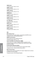
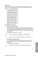
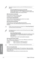
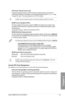
Skew Control This item contains the transmitter and receiver's rising and falling slopes and their time controllers. Adjust these items to enhance the DRAM overclocking capability and stability. Use the or keys to adjust the value. Transmitter Rising Slope [Auto] Configuration options: [Auto] [0] - [31] Transmitter Falling Slope [Auto] Configuration options: [Auto] [0] - [31] Transmitter Control Time [Auto] Configuration options: [Auto] [0] - [31] Receiver Rising Slope [Auto] Configuration options: [Auto] [0] - [31] Receiver Falling Slope [Auto] Configuration options: [Auto] [0] - [31] Receiver Control Time [Auto] Configuration options: [Auto] [0] - [31] External DIGI+ Power Control CPU Load-line Calibration [Auto] Load-line is defined by Intel® specification and affects CPU power voltage. The CPU working voltage decreases proportionally to CPU loading. Higher load-line calibration could get higher voltage and good overclocking performance, but increases the CPU and VRM thermal conditions. Select from levels 1 to 9 to adjust the CPU power voltage from 0% to 125%. Configuration options [Auto] [Level 1] - [Level 9] The actual performance boost may vary depending on your CPU specification. DO NOT remove the thermal module. The thermal conditions should be monitored. CPU VRM Switching Frequency [Auto] This item affects the VRM transient response speed and the component thermal production. Select [Manual] to configure a higher frequency for a quicker transient response speed. Configuration options: [Auto] [Manual] DO NOT remove the thermal module. The thermal conditions should be monitored. Chapter 3 ASUS SABERTOOTH Z97 MARK 2 3-21
-
 1
1 -
2
-
3
-
4
-
5
-
6
-
7
-
8
-
9
-
10
-
11
-
12
-
13
-
14
-
15
-
16
-
17
-
18
-
19
-
20
-
21
-
22
-
23
-
24
-
25
-
26
-
27
-
28
-
29
-
30
-
31
-
32
-
33
-
34
-
35
-
36
-
37
-
38
-
39
-
40
-
41
-
42
-
43
-
44
-
45
-
46
-
47
-
48
-
49
-
50
-
51
-
52
-
53
-
54
-
55
-
56
-
57
-
58
-
59
-
60
-
61
-
62
-
63
-
64
-
65
-
66
-
67
-
68
-
69
-
70
-
71
-
72
-
73
-
74
-
75
-
76
-
77
-
78
-
79
-
80
-
81
-
82
-
83
-
 84
84 -
 85
85 -
 86
86 -
 87
87 -
 88
88 -
 89
89 -
 90
90 -
 91
91 -
 92
92 -
 93
93 -
 94
94 -
95
-
96
-
97
-
98
-
99
-
100
-
101
-
102
-
103
-
104
-
105
-
106
-
107
-
108
-
109
-
110
-
111
-
112
-
113
-
114
-
115
-
116
-
117
-
118
-
119
-
120
-
121
-
122
-
123
-
124
-
125
-
126
-
127
-
128
-
129
-
130
-
131
-
132
-
133
-
134
-
135
-
136
-
137
-
138
-
139
-
140
-
141
-
142
-
143
-
144
-
145
-
146
-
147
-
148
-
149
-
150
-
151
-
152
-
153
-
154
-
155
-
156
-
157
-
158
-
159
-
160
-
161
-
162
-
163
-
164
-
165
-
166
-
167
-
168
-
169
-
170
-
171
-
172
-
173
-
174
 |
 |