Asus Terminator A7VT Terminator A7VT User Manual
Asus Terminator A7VT Manual
 |
View all Asus Terminator A7VT manuals
Add to My Manuals
Save this manual to your list of manuals |
Asus Terminator A7VT manual content summary:
- Asus Terminator A7VT | Terminator A7VT User Manual - Page 1
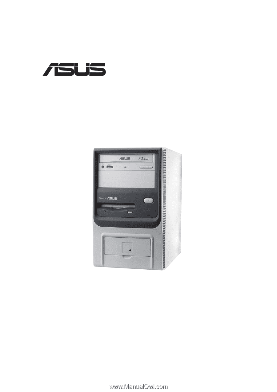
® Terminator 1 Barebone System Model A7VT User Guide - Asus Terminator A7VT | Terminator A7VT User Manual - Page 2
express written permission of ASUSTeK COMPUTER INC. ("ASUS"). Product warranty or service will not be extended if: (1) the ASUS HAS BEEN ADVISED OF THE POSSIBILITY OF SUCH DAMAGES ARISING FROM ANY DEFECT OR ERROR IN THIS MANUAL OR PRODUCT. SPECIFICATIONS AND INFORMATION CONTAINED IN THIS MANUAL - Asus Terminator A7VT | Terminator A7VT User Manual - Page 3
About this guide 8 Memory configurations 26 2.7.2 DIMM installation 27 2.8 Installing an expansion card 28 2.8.1 Expansion slots 28 2.8.2 Expansion card installation 29 2.8.3 Configuring an expansion card 29 2.8.4 Standard interrupt assignments 30 2.8.5 IRQ assignments for this motherboard - Asus Terminator A7VT | Terminator A7VT User Manual - Page 4
Power supply specifications 40 2.14.1 Input Characteristics 40 2.14.3 Over-Voltage Protection (OVP 40 2.14.2 Output Characteristics 40 Chapter 3: Starting up 3.1 Installing an operating system 42 3.2 Support CD information 42 3.2.1 Running the support CD 42 3.2.2 Utilities menu 43 3.2.3 ASUS - Asus Terminator A7VT | Terminator A7VT User Manual - Page 5
Master/Slave 75 5.4 Advanced Menu 76 5.4.1 CPU configuration 77 5.4.2 Memory configuration 78 5.4.3 Chipset configuration 79 5.4.4 PCIPnP 81 5.4.5 Onboard device configuration 82 5.4.6 USB configuration 84 5.5 Power Menu 85 5.5.1 APM configuration 86 5.5.2 Hardware monitor 89 5.6 Boot - Asus Terminator A7VT | Terminator A7VT User Manual - Page 6
. This equipment generates, uses and can radiate radio frequency energy and, if not installed and used in accordance with manufacturer's instructions, may cause harmful interference to radio communications. However, there is no guarantee that interference will not occur in a particular installation - Asus Terminator A7VT | Terminator A7VT User Manual - Page 7
connected. • If the power supply is broken, do not try to fix it by yourself. Contact a qualified service technician or your retailer. a stable surface. • If you encounter technical problems with the product, contact a qualified service technician or your retailer. Lithium-Ion Battery Warning - Asus Terminator A7VT | Terminator A7VT User Manual - Page 8
About this guide Audience This guide provides general information and installation instructions about the ASUS Terminator 1 barebone system. This guide is intended for experienced users and integrators with hardware knowledge of personal computers. How this guide is organized This guide contains the - Asus Terminator A7VT | Terminator A7VT User Manual - Page 9
Conventions used in this guide WARNING: Information to prevent injury to yourself when trying to complete a task. CAUTION: Information to prevent damage to the components when trying to complete a task. IMPORTANT: Instructions that you MUST follow to complete a task. NOTE: Tips and additional - Asus Terminator A7VT | Terminator A7VT User Manual - Page 10
System package contents Check your ASUS Terminator 1 package for the following items: 1. ASUS Terminator 1 barebone system with: • ASUS A7VT motherboard • Floppy disk drive • Optical drive (optional)* 2. Power cable and plug 3. Support CD 4. User guide * CD-ROM/CD-RW/DVD-ROM/DVD-RW If any of the - Asus Terminator A7VT | Terminator A7VT User Manual - Page 11
System Introduction Chapter 1 This chapter gives a general description of the ASUS Terminator 1 A7VT barebone system. It includes introduction on the front and rear panel features, and the internal features. ASUS Terminator 1 A7VT barebone system 11 - Asus Terminator A7VT | Terminator A7VT User Manual - Page 12
mini-tower casing, and is powered by the ASUS A7VT motherboard that supports AMD Athlon™ and AMD Duron™ processors. 1.2 Front panel The ASUS Terminator 1 barebone system is composed of the ASUS A7VT motherboard, a power supply, and a floppy disk drive in the ASUS TriOptix form factor chassis. The - Asus Terminator A7VT | Terminator A7VT User Manual - Page 13
this button to turn the system on. 5. Power LED. This LED lights up to indicate that the system is ON. 6. HDD LED. This Headphone port. This port connects a headphone with a stereo mini-plug. 10. Microphone port. This Mic (pink) port connects a microphone. ASUS Terminator 1 A7VT barebone system 13 - Asus Terminator A7VT | Terminator A7VT User Manual - Page 14
port. This port connects a joystick or game pad for playing games, and MIDI devices for audio editing. 2. Serial port. This port connects a mouse, modem, or other devices that conform with serial specification. 3. PS/2 mouse port. This green 6-pin connector is for a PS/2 mouse. 4. PS/2 keyboard port - Asus Terminator A7VT | Terminator A7VT User Manual - Page 15
the voltage supply in your area. If the voltage supply in your area is 100-127V, set the switch to 115V. If the voltage supply in your area is 200-240V, set the switch to 230V. Setting the switch to 115V in a 230V environment will seriously damage the system! ASUS Terminator 1 A7VT barebone system - Asus Terminator A7VT | Terminator A7VT User Manual - Page 16
may come with either a PFC (Power Factor Correction) or non-PFC power supply. 3 1 4 5 2 6 7 1. Game/MIDI/COM1 extension module 2. Motherboard 3. Two 5.25" drive bays (Optional CD-ROM) 4. 3.5" HDD drive bay 5. 3.5" floppy drive 6. PFC/Non-PFC power supply 7. USB/audio board 16 Chapter 1: System - Asus Terminator A7VT | Terminator A7VT User Manual - Page 17
Chapter 2 This chapter gives step-by-step instructions on how to install components into the barebone system. Basic Installation ASUS Terminator 1 A7VT barebone system 17 - Asus Terminator A7VT | Terminator A7VT User Manual - Page 18
power supply case, before handling components to avoid damaging them due to static electricity. • Hold components by the edges to avoid touching the ICs on them. • Whenever you uninstall any component, place it on a grounded antistatic pad or in the bag that came with the component. The motherboard - Asus Terminator A7VT | Terminator A7VT User Manual - Page 19
then push the inner chassis with your thumbs while pulling the panel with your other fingers. Screw 3. While supporting the front panel with one hand, place your other hand on the top rear edge of the cover and carefully lift the cover from the chassis. ASUS Terminator 1 A7VT barebone system 19 - Asus Terminator A7VT | Terminator A7VT User Manual - Page 20
switch are attached to a metal module secured to the rear panel by a screw. Power socket module screw Remove the screw to release the power socket module. Power socket module You must release the power socket module from the rear panel before detaching the drive frame to avoid breaking the - Asus Terminator A7VT | Terminator A7VT User Manual - Page 21
3. Place your thumb on the right edge of the power socket module, then slide the module to the right until it is completely detached from the rear the chassis when installing components. 5. Carefully lay the drive frame alongside the main chassis frame. ASUS Terminator 1 A7VT barebone system 21 - Asus Terminator A7VT | Terminator A7VT User Manual - Page 22
. Take note of the marked corner (with gold triangle) on the CPU. This mark should match a specific corner on the socket to ensure correct installation. Gold triangle CPU installation To install the CPU. 1. Locate the 462-pin ZIF socket on the motherboard. 22 Chapter 2: Basic Installation - Asus Terminator A7VT | Terminator A7VT User Manual - Page 23
is in place, push down the socket lever to secure the CPU. The lever clicks on the side tab to indicate that it is locked. ASUS Terminator 1 A7VT barebone system 23 - Asus Terminator A7VT | Terminator A7VT User Manual - Page 24
fan assembly to ensure optimum thermal condition and system performance. Make sure that you properly install the CPU heatsink and fan to avoid thermal problems. Follow these steps to install the CPU heatsink and fan. 1. Position the fan and heatsink assembly on top of the installed CPU such that - Asus Terminator A7VT | Terminator A7VT User Manual - Page 25
4. Connect the CPU fan cable from the assembly to the fan connector labeled CPU_FAN1. CPU fan connector (CPU_FAN1) ASUS Terminator 1 A7VT barebone system 25 - Asus Terminator A7VT | Terminator A7VT User Manual - Page 26
system memory The motherboard comes with two Double Data Rate (DDR) Dual Inline Memory Module (DIMM) sockets. These sockets support up to 2 GB system memory using unbuffered ECC or non-ECC PC2700/2100 DIMMs. 104 Pins 80 Pins A7VT ® DIMM2 DIMM1 A7VT 184-Pin DDR DIMM sockets 2.7.1 Memory - Asus Terminator A7VT | Terminator A7VT User Manual - Page 27
Follow these steps to install a DDR DIMM. 1. Locate the two DIMM sockets on the motherboard. 2. Unlock a socket by pressing the retaining clips outward. 3. Align a DIMM on the direction. DO NOT force a DIMM into a socket to avoid damaging the DIMM. ASUS Terminator 1 A7VT barebone system 27 - Asus Terminator A7VT | Terminator A7VT User Manual - Page 28
4x cards. When you buy an AGP card, make sure that you ask for one with 1.5V specification. Install only +1.5V AGP cards. The motherboard does not support 3.3V AGP cards. Make sure to unplug the power cord before adding or removing expansion cards. Failure to do so may cause you physical injury and - Asus Terminator A7VT | Terminator A7VT User Manual - Page 29
the software settings. 1. Turn on the system and change the necessary BIOS settings, if any. See Chapter 5 for information on BIOS setup. 2. Install the software drivers for the expansion card. ASUS Terminator 1 A7VT barebone system 29 - Asus Terminator A7VT | Terminator A7VT User Manual - Page 30
are usually available for ISA or PCI devices. 2.8.5 IRQ assignments for this motherboard PCI slot AGP slot USB 1.1 UHCI 1 USB 1.1 UHCI 1 USB 1.1 UHCI 1 USB 2.0 EHCI Onboard Audio Onboard LAN ABC - used - used - - DEF G H shared - - - - - used - - - - - shared - - - - - used - - - shared - Asus Terminator A7VT | Terminator A7VT User Manual - Page 31
2.9 Installing a CD-ROM drive A CD-ROM drive is an optional item in this barebone system. Refer to the instructions in this section if you acquired a model without a CD-ROM. Follow these steps to each side of the bay. 5.25-inch drive bay CD-ROM screws ASUS Terminator 1 A7VT barebone system 31 - Asus Terminator A7VT | Terminator A7VT User Manual - Page 32
a power cable from the power supply to the power connector audio cable IDE ribbon cable Red stripe to Pin 1 Power cable (P1) 8. Connect the other end of the IDE ribbon cable to the secondary IDE connector (black connector labeled SEC_IDE) on the motherboard. 9. Connect the other end of the audio - Asus Terminator A7VT | Terminator A7VT User Manual - Page 33
screw holes align with the holes on the bay marked HDD. 4. Secure the drive with two screws on each side of the bay. HDD screws ASUS Terminator 1 A7VT barebone system 33 - Asus Terminator A7VT | Terminator A7VT User Manual - Page 34
5. Connect a power cable from the power supply to the power connector at the back of the HDD. Use the cable with the the cable with Pin 1 on the IDE interface. Red stripe to Pin 1 IDE ribbon cable Power cable (P3) 7. Connect the other end of the IDE ribbon cable to the primary IDE connector (blue connector - Asus Terminator A7VT | Terminator A7VT User Manual - Page 35
Ground PANEL HDLED RESET SMI PWRBTN* * Requires an ATX power supply. • Connect the power switch and power LED cables to their respective leads in the PANEL connector on the motherboard. • Connect the HDD LED cable to the 2-pin lead marked HDLED. ASUS Terminator 1 A7VT barebone system 35 - Asus Terminator A7VT | Terminator A7VT User Manual - Page 36
panel I/O ports and the connectors to the motherboard. USB T: Port0 B: Port1 J1 UAEX HPHONE1 J2 MIC ® Connect to MIC_LOUT connector on the motherboard Connect to USB34 connector on the motherboard Connector locations on the motherboard USB34 USB56 MIC_LOUT connector (for Microphone/Line Out - Asus Terminator A7VT | Terminator A7VT User Manual - Page 37
perfectly to the chassis edge. Protruding tab 3. Turn the chassis upright. 4. Place the cover over the chassis leaving about two inches from the rear panel. ASUS Terminator 1 A7VT barebone system 37 - Asus Terminator A7VT | Terminator A7VT User Manual - Page 38
5. Fit the rail tabs on the sides and bottom of the cover to the edges of the chassis. Rail tabs 6. Push the cover towards the rear until it fits. The locking tab snaps into the hole on the chassis indicating that the cover is in place. Locking tab Locking tab hole Firmly push the cover to ensure - Asus Terminator A7VT | Terminator A7VT User Manual - Page 39
2.13 Connecting external devices The figure below shows the specific connectors and devices that you can connect to the rear panel ports. Serial PS/2 KB VGA Line Out Line In Mic RJ-45 Game/MIDI PS/2 Mouse Parallel AC USB ASUS Terminator 1 A7VT barebone system 39 - Asus Terminator A7VT | Terminator A7VT User Manual - Page 40
2.14 Power supply specifications 2.14.1 Input Characteristics Input Voltage Range Range 1 Range 2 Input Frequency Range Maximum Input ac Current Inrush Current Efficiency Min Nom Max 90V 115V 135V 180V - Asus Terminator A7VT | Terminator A7VT User Manual - Page 41
Chapter 3 This chapter helps you power up your system and install drivers and utilities that came with the support CD. Starting up ASUS Terminator 1 A7VT barebone system 41 - Asus Terminator A7VT | Terminator A7VT User Manual - Page 42
contains useful software and several utility drivers that enhance the motherboard features. The contents of the support CD are subject to change at any time without notice. Visit the ASUS website for updates. 3.2.1 Running the support CD To begin using the support CD, simply insert the CD into - Asus Terminator A7VT | Terminator A7VT User Manual - Page 43
at a healthy operating condition. ASUS Update This item installs the ASUS Update. This program allows you to download the latest version of the BIOS from the ASUS website. Microsoft® Direct X Driver This item installs the Microsoft® Direct X driver. ASUS Terminator 1 A7VT barebone system 43 - Asus Terminator A7VT | Terminator A7VT User Manual - Page 44
This item installs the PC-cillin 2002 anti-virus software. View the PC-cillin online help for detailed information. ADOBE Acrobat Reader This item installs the Adobe Acrobat® Reader®. The Acrobat Reader software is for viewing files saved in Portable Document Format (PDF). ASUS Screen Saver This - Asus Terminator A7VT | Terminator A7VT User Manual - Page 45
the specified information. Motherboard Info Displays the general specifications of the motherboard. The screen image below is for general reference only. The support CD will automatically detect the motherboard information and display it on your screen. ASUS Terminator 1 A7VT barebone system 45 - Asus Terminator A7VT | Terminator A7VT User Manual - Page 46
Browse this CD Displays the support CD contents in graphical format. Technical support form Displays the ASUS Technical Support Request Form that you have to fill out when requesting technical support. Filelist Displays the contents of the support CD and a brief description of each in text format. - Asus Terminator A7VT | Terminator A7VT User Manual - Page 47
the Windows® Start button, point to Programs, and then ASUS Utility, and then click Probe Vx.xx. The PC Probe icon appears on the taskbar system tray indicating that ASUS PC Probe is running. Clicking the icon allows you to see the status of your PC. ASUS Terminator 1 A7VT barebone system 47 - Asus Terminator A7VT | Terminator A7VT User Manual - Page 48
Using ASUS PC Probe Monitoring Monitor Summary Shows a summary of the items being monitored. Temperature Monitor Shows the PC temperature. Temperature Warning threshold adjustment (Move the slider up to increase the threshold level or down to decrease the threshold level) Fan Monitor Shows the PC - Asus Terminator A7VT | Terminator A7VT User Manual - Page 49
History Lets you record the monitoring activity of a certain component of your PC for future reference. Fan Control Lets you enable/disable Smart Fan Control. and free space of the PC's hard disk drives and the file allocation table or file system used. ASUS Terminator 1 A7VT barebone system 49 - Asus Terminator A7VT | Terminator A7VT User Manual - Page 50
Device Summary Shows a summary of devices present in your PC. DMI Explorer Shows information pertinent to the PC, such as CPU type, CPU speed, and internal/external frequencies, and memory size. Utility Lets you run programs outside of the ASUS Probe modules. To run a program, click Execute Program - Asus Terminator A7VT | Terminator A7VT User Manual - Page 51
Service Provider (ISP). Follow these steps to use the ASUS Update. 1. Launch the utility from your Windows Start menu: Programs/AsusUpdate Vx.xx.xx/ AsusUpdate The ASUS Update initial screen appears. 2. Select your desired update method, then click Next. ASUS Terminator 1 A7VT barebone system - Asus Terminator A7VT | Terminator A7VT User Manual - Page 52
updating/ downloading from the Internet, select the ASUS FTP site nearest you to avoid network traffic, or choose Auto Select. Click Next. 4. From the FTP site, select the BIOS version that you wish to download. Click Next. 5. Follow the instructions on the succeeding screens to complete the update - Asus Terminator A7VT | Terminator A7VT User Manual - Page 53
Chapter 4 This chapter gives information about the motherboard that came with the system.This chapter includes the motherboard layout, jumper settings, and connector locations. Motherboard Info ASUS Terminator T1 A7VT barebone system 53 - Asus Terminator A7VT | Terminator A7VT User Manual - Page 54
4.1 Introduction The ASUS A7VT motherboard comes already installed in the ASUS Terminator 1 A7VT barebone system. This chapter provides technical information about the motherboard for future upgrades or system reconfiguraiton. 4.2 Motherboard layout PS/2 T:Mouse B:Keyboard VGA IOC_MB ATX12V 23cm - Asus Terminator A7VT | Terminator A7VT User Manual - Page 55
mode. • Make sure to set the jumpers to +5VSB if you want to wake up the system from S3, S4, and S5 sleep mode. A7VT ® A7VT USB device wake-up 2 USBPWR12 1 +5V 12 USBPWR34 +5V 12 USBPWR56 +5V 3 2 +5VSB (Default) 23 +5VSB (Default) 23 +5VSB (Default) ASUS Terminator T1 A7VT barebone system 55 - Asus Terminator A7VT | Terminator A7VT User Manual - Page 56
the power cord and turn ON the computer. 6. Hold down the key during the boot process and enter BIOS setup to re-enter data. A7VT ® A7VT Clear RTC RAM CLRTC 12 23 Clear CMOS Normal (Default) Except when clearing the RTC RAM, never remove the cap. 56 Chapter 4: Motherboard information - Asus Terminator A7VT | Terminator A7VT User Manual - Page 57
the jumper to 2-3 only when your CPU FSB frequency is 100 MHz. If your CPU FSB frequency is 133/166 MHz, set the jumper to 1-2. A7VT ® FSB 12 23 133/166 100 A7VT External frequency selection (Default) ASUS Terminator T1 A7VT barebone system 57 - Asus Terminator A7VT | Terminator A7VT User Manual - Page 58
has three connectors: a blue connector for the primary IDE connector on the motherboard, a black connector for an Ultra DMA 133/100/66 IDE slave device IDE cable for Ultra DMA 133/100/66 IDE devices. A7VT ® A7VT IDE connectors SEC_IDE PRI_IDE NOTE: Orient the red markings (usually zigzag - Asus Terminator A7VT | Terminator A7VT User Manual - Page 59
to receive stereo audio input from sound sources such as an optical drive, TV tuner, or MPEG card. Left Audio Channel Ground Right Audio Channel A7VT ® A7VT Internal audio connectors AUX (White) Right Audio Channel Ground CD (Black) Left Audio Channel ASUS Terminator T1 A7VT barebone system 59 - Asus Terminator A7VT | Terminator A7VT User Manual - Page 60
Volts -5.0 Volts Ground Ground Ground Power Supply On Ground -12.0Volts +3.3Volts A7VT ® ATX12V COM +12V DC A7VT ATX power connectors COM +12V DC Make sure to connect the 4-pin ATX +12V power plug; otherwise, the system does not boot up. 5. Front panel audio connector (5-1 pin MIC_LOUT) This - Asus Terminator A7VT | Terminator A7VT User Manual - Page 61
the motherboard components. These are not jumpers! Do not place jumper caps on the fan connectors! 7. IO extension module connector (22-pin IOC_MB) This connector is for the CGAEX extension module. A7VT ® A7VT CGAEX extension module COM1 GAME ® CGAEX IOC_DC ASUS Terminator T1 A7VT barebone - Asus Terminator A7VT | Terminator A7VT User Manual - Page 62
connector supports several chassis-mounted functions. PLED SPEAKER +5VSB PLED +5V Ground Ground Speaker +5 V HDLED NC ExtSMI# Ground PWR Ground Reset Ground A7VT ® A7VT System panel connector HDLED RESET SMI PWRBTN* * Requires an ATX power supply. 62 Chapter 4: Motherboard information - Asus Terminator A7VT | Terminator A7VT User Manual - Page 63
is for the system power button. Pressing the power button turns the system on or puts the system in sleep or soft-off mode depending on the BIOS settings. Pressing the power switch for more than four seconds while the system is ON turns the system OFF. ASUS Terminator T1 A7VT barebone system 63 - Asus Terminator A7VT | Terminator A7VT User Manual - Page 64
64 Chapter 4: Motherboard information - Asus Terminator A7VT | Terminator A7VT User Manual - Page 65
Chapter 5 This chapter tells how to change system settings through the BIOS Setup menus. It includes detailed descriptions of the BIOS parameters. BIOS Information ASUS Terminator 1 A7VT barebone system 65 - Asus Terminator A7VT | Terminator A7VT User Manual - Page 66
case you need to restore the BIOS in the future. Copy the original motherboard BIOS using the ASUS Update or AFLASH utilities. • Visit the ASUS website and download the latest BIOS file for this motherboard using the ASUS Update utility. 5.1.1 Creating a bootable floppy disk 1. Do either one of the - Asus Terminator A7VT | Terminator A7VT User Manual - Page 67
1. Download the latest BIOS file from the ASUS website. (www.asus.com). Rename the file to *.BIN and save it to the bootable floppy disk you created earlier. 2. Insert the disk that contains the new BIOS file into the floppy drive. 3. Reboot the computer. ASUS Terminator 1 A7VT barebone system 67 - Asus Terminator A7VT | Terminator A7VT User Manual - Page 68
4. Press + during POST to display the following screen. 5. AWDFLASH checks the new BIOS file from the floppy disk. 6. After verification, AWDFLASH flashes the new BIOS file. Do not shut down the computer during the flash process. 7. After the new BIOS file is copied, the computer returns - Asus Terminator A7VT | Terminator A7VT User Manual - Page 69
Checking for floppy... Floppy found! Reading file "a7vt.bin". Completed. Start flashing... DO NOT shut down or reset the system while updating the BIOS! Doing so may cause system boot failure! 4. When the BIOS update process is complete, reboot the system. ASUS Terminator 1 A7VT barebone system 69 - Asus Terminator A7VT | Terminator A7VT User Manual - Page 70
BIOS in Windows® environment. This utility is available in the support CD that comes with the motherboard package. ASUS Update requires an Internet connection either through a network or an Internet Service Provider (ISP). Go to section "3.3.2 ASUS Update" for details on how to update the - Asus Terminator A7VT | Terminator A7VT User Manual - Page 71
enable the security password feature or make changes to the power management settings. This requires you to reconfigure your system using and record them in the CMOS RAM of the Flash ROM. The Flash ROM on the motherboard stores the Setup utility. When you ASUS Terminator 1 A7VT barebone system 71 - Asus Terminator A7VT | Terminator A7VT User Manual - Page 72
changes to the basic system configuration. ADVANCED Use this menu to enable and make changes to the advanced features. POWER Use this menu to configure and enable Power Management features. BOOT Use this menu to configure the default system device used to locate and load the Operating System - Asus Terminator A7VT | Terminator A7VT User Manual - Page 73
to load the Setup default values. While moving around through the Setup program, note that explanations appear in the Item Specific Help window located to the right of each menu. This window displays the help text for the currently highlighted field. ASUS Terminator 1 A7VT barebone system 73 - Asus Terminator A7VT | Terminator A7VT User Manual - Page 74
in.] IDE Primary Master [Auto] IDE Primary Slave [Pioneer CD-ROM A] IDE Secondary Master [None] IDE Secondary Slave [None] Installed Memory [256 MB] Select Menu Item Specific Help Change the internal clock. 5.3.1 System Time [xx:xx:xx] Sets the system to the time that you specify (usually - Asus Terminator A7VT | Terminator A7VT User Manual - Page 75
None Select Menu Item Specific Help Press [Enter] manually enter the IDE hard disk drive parameters. Refer to the next section for details. Before attempting to configure a hard disk drive, make sure you have the correct configuration information supplied ASUS Terminator 1 A7VT barebone system 75 - Asus Terminator A7VT | Terminator A7VT User Manual - Page 76
changing the settings of the Advanced menu items. Incorrect field values may cause the system to malfunction. CPU Configuration Memory Configuration Chipset PCIPnP Onboard Device Configuration USB Configuration Select Menu Item Specific Help Press [Enter] to Set. 76 Chapter 5: BIOS information - Asus Terminator A7VT | Terminator A7VT User Manual - Page 77
5.4.1 CPU configuration The items in this menu show the CPU-related information auto-detected by the BIOS. CPU Configuration CPU Type CPU Speed Cache RAM Current FSB Frequency AMD Athlon (tm) 1000 MHz 256 K 100 MHz Select Menu Item Specific Help ASUS Terminator 1 A7VT barebone system 77 - Asus Terminator A7VT | Terminator A7VT User Manual - Page 78
up menu with the configuration options. Memory Configuration Current DRAM Frequency 133 MHz Write Recovery Time [3T] tWTR [2T] Select Menu Item Specific Help Set DRAM Frequency. DRAM Clock [By SPD] Sets the . Select [Manual] to set the DRAM Timing manually. Select [Safe] to set the DRAM - Asus Terminator A7VT | Terminator A7VT User Manual - Page 79
[PCI slot] AGP Bridge Configuration Select Menu Item Specific Help AGP Display Switch [Auto] Select [Auto] : Graphics Aperture Size [64MB] Allows you to select the size of mapped memory for AGP graphic data. Configuration options: [1G] [512M] [256M] [128M ASUS Terminator 1 A7VT barebone system 79 - Asus Terminator A7VT | Terminator A7VT User Manual - Page 80
is a data transfer protocol that combines PCI and AGP protocols to support continuous data transfer directly from the chipset to the AGP. Configuration options: [Disabled] [Enabled] Onboard Video Memory [32M] This item allows you to set the memory space reserved for the VGA frame buffer (display - Asus Terminator A7VT | Terminator A7VT User Manual - Page 81
] [Auto] [Disabled] [Enabled] Select Menu Item Specific Help Plug & Play OS [No] Select [Yes] Manual], you can assign the available IRQ resources to the PCI devices. Configuration options: [Auto] [Manual to [Enabled] corrects this problem. If you are using ASUS Terminator 1 A7VT barebone system 81 - Asus Terminator A7VT | Terminator A7VT User Manual - Page 82
with the configuration options. PCIPnP Onboard LAN Boot ROM AC97 Audio Onboard LAN Serial Port1 Address Parallel Port Address Parallel Port Mode [ECP+EPP] [EPP1.7] [3] [201] [Disabled] 10 Select Menu Item Specific Help Onboard LAN Boot ROM [Disabled] Allows you to enable or disable the optional - Asus Terminator A7VT | Terminator A7VT User Manual - Page 83
the game port. Configuration options: [Disabled] [201] [209] Midi Port Address [Disabled] Sets the I/O address for the MIDI I/O port. Configuration options: [Disabled] [330] [300] [290] ASUS Terminator 1 A7VT barebone system 83 - Asus Terminator A7VT | Terminator A7VT User Manual - Page 84
to display a pop-up menu with the configuration options. USB Configuration USB 1.1 Controller USB 2.0 Controller USB Legacy Support [Enabled] [Enabled] [Enabled] Select Menu Item Specific Help Enable or Disable the USB 1.1 Controller. USB 1.1 Controller [Enabled] Allows you to enable or disable - Asus Terminator A7VT | Terminator A7VT User Manual - Page 85
Allows you to select the ACPI stated used for system suspend. Configuration options: [S1(POS)] [S3(STR)] [S1&S3] ACPI APIC Support [Enabled] Allows you enable or disable the ACPI feature on the operating system. Configuration options: [Enabled] [Disabled] ASUS Terminator 1 A7VT barebone system 85 - Asus Terminator A7VT | Terminator A7VT User Manual - Page 86
. Configuration options: [Hot key] [Password] PS2KB Wakeup from S3/S4/S5 [Disabled] Allows you to use specific keys on the keyboard to turn on the system. This feature requires an ATX power supply that provides at least 1A on the +5VSB lead. Configuration options: [Disabled] [Ctrl+F1] [Ctrl+F2 - Asus Terminator A7VT | Terminator A7VT User Manual - Page 87
while the computer is off causes an initialization string that turns the system power on. Power On By RTC Alarm [Disabled] Allows you to enable or disable RTC video off feature to monitor power management. Configuration options: [Suspend -> Off] [Always On] ASUS Terminator 1 A7VT barebone system 87 - Asus Terminator A7VT | Terminator A7VT User Manual - Page 88
off the system. Configuration options: [Suspend] [Instant-Off] Restore on AC Power Loss [Power Off] Allows you to set whether or not to reboot the system after power interruptions. [Power Off] leaves your system off, [Power On] reboots the system, and [Last State] sets the system back to the state - Asus Terminator A7VT | Terminator A7VT User Manual - Page 89
automatically detects and displays the power supply and CPU temperatures in these fields. Chassis Fan Speed [xxxxRPM] CPU Fan Speed [xxxxRPM] The onboard hardware monitor automatically detects the CPU and chassis fan speeds in rotations per minute (RPM). ASUS Terminator 1 A7VT barebone system 89 - Asus Terminator A7VT | Terminator A7VT User Manual - Page 90
VCORE Voltage, +3.3V Voltage, +5V Voltage, +12V Voltage The onboard hardware monitor automatically detects the voltage output through the onboard voltage regulators. 90 Chapter 5: BIOS information - Asus Terminator A7VT | Terminator A7VT User Manual - Page 91
Select Menu Item Specific Help 5.6.1 Boot Device Priority Boot Device Priority 1st Boot Device 2nd Boot Device 3rd Boot Device 4th Boot Device [Removable] [Hard Disk] [CDROM] [Disabled] Select Menu Item Specific Help Select your Boot Device Priority ASUS Terminator 1 A7VT barebone system 91 - Asus Terminator A7VT | Terminator A7VT User Manual - Page 92
Disabled] 5.6.2 Removable drives Removable Drives 1. Floppy Disks Select Menu Item Specific Help Use or arrow to select a device, 5.6.3 Hard Disk Drives Hard Disk Drives 1. Bootable Add-in Cards Select Menu Item Specific Help Use or arrow to select a device, then press - Asus Terminator A7VT | Terminator A7VT User Manual - Page 93
(Msec) 250 OS Select for DRAM > 64MB [Non-OS2] Halt On [All Errors] Item Specific Help Allows the system to skip certain tests while booting. This will decrease the time needed to boot to boot the system. Configuration options: [Enabled] [Disabled] ASUS Terminator 1 A7VT barebone system 93 - Asus Terminator A7VT | Terminator A7VT User Manual - Page 94
] Boot Up Num-Lock Status [On] Allows you to select the power-on state for the NumLock. Configuration options: [On] [Off] Typematic ] Select [OS2] only when you are using an OS2 operating system with greater than 64MB RAM. Otherwise, set to [Non-OS2]. Configuration options: [Non-OS2] [OS2] Halt On - Asus Terminator A7VT | Terminator A7VT User Manual - Page 95
Security Supervisor Password User Password Password Check Clear Clear [Setup] Select Menu Item Specific Help Supervisor password controls full access, to change password. Supervisor Password to boot the system preventing unauthorized use. ASUS Terminator 1 A7VT barebone system 95 - Asus Terminator A7VT | Terminator A7VT User Manual - Page 96
RAM. The RAM data containing the password information is powered by the onboard button cell battery. If you need to erase the CMOS RAM, refer to section "2.6 Jumpers" for instructions Changes Load Setup Default Discard Changes Select Menu Item Specific Help This option saves data to CMOS and exits - Asus Terminator A7VT | Terminator A7VT User Manual - Page 97
non-volatile RAM. Discard Changes This option allows you to discard the selections you made and restore the previously saved values. After selecting this option, a confirmation appears. Select [Yes] to discard any changes and load the previously saved values. ASUS Terminator 1 A7VT barebone system - Asus Terminator A7VT | Terminator A7VT User Manual - Page 98
98 Chapter 5: BIOS information
-
 1
1 -
 2
2 -
 3
3 -
 4
4 -
 5
5 -
 6
6 -
 7
7 -
8
-
9
-
10
-
11
-
12
-
13
-
14
-
15
-
16
-
17
-
18
-
19
-
20
-
21
-
22
-
23
-
24
-
25
-
26
-
27
-
28
-
29
-
30
-
31
-
32
-
33
-
34
-
35
-
36
-
37
-
38
-
39
-
40
-
41
-
42
-
43
-
44
-
45
-
46
-
47
-
48
-
49
-
50
-
51
-
52
-
53
-
54
-
55
-
56
-
57
-
58
-
59
-
60
-
61
-
62
-
63
-
64
-
65
-
66
-
67
-
68
-
69
-
70
-
71
-
72
-
73
-
74
-
75
-
76
-
77
-
78
-
79
-
80
-
81
-
82
-
83
-
84
-
85
-
86
-
87
-
88
-
89
-
90
-
91
-
92
-
93
-
94
-
95
-
96
-
97
-
98
 |
 |
®
User Guide
Barebone System
Model A7VT
Terminator 1