Behringer PMP1000 Manual - Page 14
Wiring Examples - parts
 |
View all Behringer PMP1000 manuals
Add to My Manuals
Save this manual to your list of manuals |
Page 14 highlights
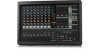
14 EUROPOWER PMP6000/PMP4000/PMP1000 User Manual 4.3 Loudspeaker connections Your power mixer is equipped with high-quality loudspeaker connectors , which ensure safe and trouble-free operation. The connector was especially developed for high-power loudspeakers. Once it is plugged in, it safely locks into position and cannot be accidentally disengaged. It prevents the occurrence of electrical shock and ensures the correct polarity. Each of the loudspeaker jacks carries only the assigned single signal (see the information given on the rear panel of the power mixer). 5. Wiring Examples Loudspeaker connection (monitor mix) Professional speaker connector (compatible with Neutrik Speakon connectors) 1+ 1+ 2- 1- 1- 2- 2+ front view 2+ rear view Fig. 4.6: Professional speaker connector with polarity allocation Please be sure to only use commercial cables (type NL4FC) for connecting your loudspeakers to the power mixer. Please check the pin assignment of your loudspeakers and cables dependent on the PMP speaker output you choose. EUROPOWER PMP6000/PMP4000/PMP1000 OUTPUT A 1+ 1- 2+ 2- MAIN L x x MONITOR x x MONO x x OUTPUT B x x OUTPUT B 1+ 1- 2+ 2- MAIN R x x MONO x x MONO x x BRIDGE x x Tab. 4.1: Polarity configuration of speaker connectors PMP1000 PMP4000 PMP6000 (part view) 2 x BEHRINGER EUROLIVE Stack (B1800X & B1220, both passive) Loudspeaker connection (monitor mix) front panel (part view) Footswitch Link Output 2 x BEHRINGER F1220D (active) Fig. 5.1: Stereo operation For stereo operation the POWER AMP switch (27) must be set to its upper position (MAIN or MAIN L/MAIN R). Outputs A and B provide the stereo main signal for passive speakers. The preamp monitor output is connected to two parallel active speakers, which are used as on-stage monitors. Use the footswitch to enable/ disable the effects processor. OUTPUT B 1+ OUTPUT B 1+ 8 Ω 1- 1- 4 Ω BRIDGE 1+ 2+ Fig. 4.7: Pin assignment 8 Ω 4 Ω 16 Ω 8 Ω
-
 1
1 -
2
-
3
-
4
-
5
-
6
-
7
-
8
-
 9
9 -
 10
10 -
 11
11 -
 12
12 -
 13
13 -
 14
14 -
 15
15 -
 16
16 -
 17
17 -
 18
18 -
 19
19 -
20
-
21
-
22
-
23
-
24
 |
 |
