Behringer PMP1000 Manual - Page 8
Control Elements - mixer
 |
View all Behringer PMP1000 manuals
Add to My Manuals
Save this manual to your list of manuals |
Page 8 highlights
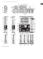
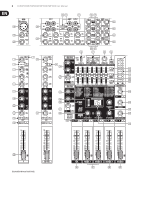
8 EUROPOWER PMP6000/PMP4000/PMP1000 User Manual (66) (69) (70) (67) (68) EUROPOWER PMP6000 REAR PANEL (72) (71) 2. Control Elements A detailed description of all functions of your power mixer can be found in the following chapters. Please also refer to the enclosed sheet with the numbered illustrations to get a good overview of the control layout. 2.1 Mono and stereo channels (1) Use the GAIN control to adjust the input gain. Be sure to set this control fully counter-clockwise before you connect or disconnect a signal source to an input. GAIN controls both the microphone and the LINE input. The black scale shows the microphone gain (+10 to +60 dB on channels with XENYX MIC PREAMPS and 0 to +40 dB on conventional microphone inputs; PMP1000 only, channels 5/6 and 7/8). The "LINE" scale indicates the sensitivity of the LINE input, ranging from +10 to -40 dBu. PMP1000: The mono/stereo combination channels 5/6 and 7/8 have a sensitivity of +20 to -20 dBu. (2) The LEVEL SET LED illuminates when an optimum operating level has been adjusted. (3) The mono channels are equipped with a high-slope LOW CUT filter eliminating unwanted low-frequency signals like rumble noise. (4) PMP4000/PMP6000 (stereo channels): Press the A/B button to switch from 1/4" jacks to RCA connectors, and vice versa. Position "A" = 1/4" jacks; position "B" = RCA connectors. (5) The HIGH control in the EQ section governs the high frequency range of the respective channel. (6) Use the MID control to boost or cut the midrange frequencies. (7) PMP6000: The PMP6000 has an additional semi-parametric filter for the midrange frequencies in the mono channels (tunable from 100 Hz to 8 kHz). Adjust the boost/cut with the MID control, and the frequency with the FREQ control. The stereo channels contain a stereo EQ section. The cut-off frequencies of the high and low bands are 12 kHz and 80 Hz respectively, while the center frequencies of the high-mid and low-mid bands are 3 kHz and 400 Hz respectively. (8) The LOW control allows you to boost/cut the low frequency range. (9) With the MON(ITOR) control you can adjust the volume of each channel in the monitor mix. (10) The PMP4000 and PMP6000 feature a second MON control (MON 2) for the volume of the second monitor bus. (11) The FX control determines the signal level sent from each channel to the built-in effects processor; this signal is also present at the FX SEND jack (see (64)). (12) The PMP6000 has two FX controls (FX 1 and FX 2), so that you can use two effects simultaneously. Accordingly, the PMP6000 also has two effect aux buses, which have one output jack in common (see (46) and (64)). ◊ Please note that the effects processor signal will be inaudible, as long as the FX TO MON/MAIN controls (40), (41), (42) are set fully counter-clockwise. (13) The PAN(ORAMA) control determines the position of the channel signal in the stereo main mix. (14) The BAL(ANCE) control for the stereo channels corresponds to the PAN control for the mono channels. It determines the relative volume of the left and right input signals before they are routed to the stereo main output. (15) PMP4000/PMP6000: When you press the PFL button (Pre Fader Listening) the left LED (34) shows the pre-fader input gain of the channel. Adjust the optimum input gain (0 dB) with the GAIN control (1). When PFL is on, the corresp onding LED illuminates. If the LEVEL SET LED (2) is illuminated constantly, the signal is within the optimum operating level range. However, if the CLIP LED indicates that the input gain is too high, you should reduce the level slightly with the GAIN control. The CLIP LED should never be illuminated all the time, only with signal peaks. (16) The MUTE switch mutes the channel in the main mix. The pre-fader signals (monitor buses) remain operative. When MUTE is pressed, the corresponding control LED illuminates. (17) The channel fader controls the channel signal level in the main mix. 2.1.1 Input section (18) Each mono input channel is equipped with a balanced microphone input (XLR connector) which provides +48 V phantom power for condenser microphones at the touch of a button (see rear panel). PMP1000: The two stereo channels 5/6 and 7/8 have an additional balanced XLR microphone input with +48 V phantom power. ◊ Be sure to switch off your audio system before you activate the phantom power supply to protect your monitor speakers from switch-on thumps. (19) Each mono input features one LINE IN connector (1/4" jack), which can be used with either balanced or unbalanced signals. ◊ Please remember to use either the microphone or the line input on a specific channel. Never use both at the same time! ◊ When you connect a mono line signal to a stereo channel, always use the left input. The mono signal will then be reproduced by both sides equally.
-
 1
1 -
2
-
 3
3 -
 4
4 -
 5
5 -
 6
6 -
 7
7 -
 8
8 -
 9
9 -
 10
10 -
 11
11 -
 12
12 -
 13
13 -
14
-
15
-
16
-
17
-
18
-
19
-
20
-
21
-
22
-
23
-
24
 |
 |
