Biostar TFORCE 550 TForce 550 user's manual
Biostar TFORCE 550 Manual
 |
View all Biostar TFORCE 550 manuals
Add to My Manuals
Save this manual to your list of manuals |
Biostar TFORCE 550 manual content summary:
- Biostar TFORCE 550 | TForce 550 user's manual - Page 1
TForce 550 Setup Manual FCC Information and Copyright This equipment has been tested and found to radiate radio frequency energy and, if not installed and used in accordance with the instructions, may cause harmful interference to radio communications. There is no guarantee that interference will - Biostar TFORCE 550 | TForce 550 user's manual - Page 2
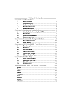
4.3 How RAID Works 21 5.1: T-Power Introduction 24 5.2: T-Power BIOS Feature 25 5.3 T-Power Windows Feature 33 Chapter 6: Useful Help 42 6.1 Driver Installation Note 42 6.2 Award BIOS Beep Code 43 6.3 Extra Information 43 6.4 Troubleshooting 45 Appendencies: SPEC In Other - Biostar TFORCE 550 | TForce 550 user's manual - Page 3
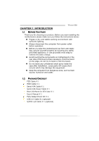
TForce 550 CHAPTER 1: INTRODUCTION 1.1 BEFORE YOU START Thank you for choosing our product. Before you start installing the motherboard, please make sure you follow the instructions below: „ Prepare a dry and stable working X 1 User's Manual X 1 Fully Setup Driver CD X 1 USB 2.0 Cable X1 (optional) - Biostar TFORCE 550 | TForce 550 user's manual - Page 4
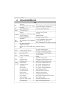
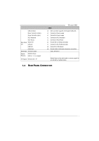
Manual 1.3 MOTHERBOARD FEATURES SPEC Socket AM2 AMD 64 Architecture enables 32 and 64 bit computing CPU AMD Athlon 64 / Athlon 64 FX / Sempron Supports Hyper Transport and Cool=n=Quiet processors FSB Support HyperTransport Support up to 1000 MHz Bandwidth Chipset nVIDIA nForce 550 - Biostar TFORCE 550 | TForce 550 user's manual - Page 5
Audio Jack Board Size ATX Form Factor Special Features NVIDIA nTunes RAID 0 / 1 / 0+1support OS Support Windows 2K / XP TForce 550 SPEC x2 Each connector supports devices x6 Provide Audio-In/Out and microphone connection 219 x 304 (mm) Biostar Reserves the right to add or remove support for any - Biostar TFORCE 550 | TForce 550 user's manual - Page 6
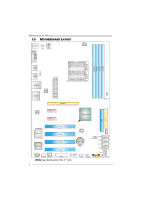
Motherboard Manual 1.5 MOTHERBOARD LAYOUT JCFAN1 JKBMS1 JKBMSV1 JATXPWR2 JCOM1 DDR2A1 DDR2B1 DDR2A2 DDR2B2 Socket A M2 JUSB3 JUSBV2 JUSB4 JATXPWR1 JUSBLAN1 LAN JAUDIO1 Codec PEX1_1 PEX1_2 PEX16_1 JDDRII_2.2V nForce 550 FDD1 IDE1 PCI1 JNFAN1 Super I/O PCI2 BIOS PCI3 BAT1 PCI4 LED1 - Biostar TFORCE 550 | TForce 550 user's manual - Page 7
TForce 550 CHAPTER 2: HARDWARE INSTALLATION 2.1 INSTALLING CENTRAL PROCESSING UNIT (CPU) Step 1: Remove the socket protection cap. Step 2: Pull the lever toward direction A from the socket and then raise the lever up to a 90-degree angle. Step 3: Look for the white triangle on socket, and the gold - Biostar TFORCE 550 | TForce 550 user's manual - Page 8
Motherboard Manual Step 4: Hold the CPU down firmly, and then close the lever toward direct B to complete the installation. Step 5: Put the CPU Fan on the CPU and buckle it. Connect the CPU FAN power cable to the JCFAN1. This completes the installation. 2.2 FAN HEADERS These fan headers support - Biostar TFORCE 550 | TForce 550 user's manual - Page 9
TForce 550 JSFAN1/JSFAN2: System Fan Header JSFAN1 Pin Assignment 1 Ground 2 Smart Fan Control 1 3 FAN RPM rate JSFAN2 sense 3 JSFAN2 31 Pin Assignment JSFAN1 1 2 Ground +12V 3 NC JNFAN1: North Bridge Fan Header JNFAN1 13 Pin Assignment 1 Ground 2 +12V 3 FAN RPM rate sense - Biostar TFORCE 550 | TForce 550 user's manual - Page 10
Motherboard Manual 2.3 INSTALLING SYSTEM MEMORY DDR2A1 DDR2B1 DDR2A2 DDR2B2 1. Unlock a DIMM chip snap back in place and the DIMM is properly seated. B. Memory Capacity DIMM Socket Location DDR/DDR2 Module DDR2A1 256MB/512MB/1GB *1 DDR2B1 256MB/512MB/1GB *1 DDR2A2 256MB/512MB/1GB *1 - Biostar TFORCE 550 | TForce 550 user's manual - Page 11
TForce 550 C. Dual Channel Memory installation To trigger the Dual Channel function of the motherboard, the memory module must meet the following requirements: Install memory module of the same density in pairs, shown in the following table. Duual Channel Status - Biostar TFORCE 550 | TForce 550 user's manual - Page 12
Motherboard Manual 2.4 CONNECTORS AND SLOTS FDD1: Floppy Disk Connector The motherboard provides a standard floppy disk connector that supports 360K, 720K, 1.2M, 1.44M and 2.88M floppy disk types. This connector supports the provided floppy drive ribbon cables. 34 33 2 1 IDE1: Hard Disk - Biostar TFORCE 550 | TForce 550 user's manual - Page 13
TForce 550 PEx16-1: PCI-Express bandwidth up to 250MB/s per direction; 500MB/s in total. - PCI-Express supports a raw bit-rate of 2.5Gb/s on the data pins. - 2X PEX1_1 PEX1_2 PCI1~PCI4: Peripheral Component Interconnect Slots This motherboard is equipped with 4 standard PCI slots. PCI stands for - Biostar TFORCE 550 | TForce 550 user's manual - Page 14
Motherboard Manual CHAPTER 3: HEADERS & JUMPERS SETUP 3.1 HOW TO SETUP JUMPERS The illustration shows how to set up jumpers. When the jumper cap is placed on pins, the - Biostar TFORCE 550 | TForce 550 user's manual - Page 15
TForce 550 JATXPWR1: ATX Power Source Connector This connector allows user to connect 24-pin power connector on Ground JATXPWR2: ATX Power Source Connector By connecting this connector, it will provide +12V to CPU power circuit. 21 4 3 Pin Assignment 1 +12V 2 +12V 3 Ground 4 Ground 13 - Biostar TFORCE 550 | TForce 550 user's manual - Page 16
Motherboard Manual JUSB1/JUSB2: Headers for USB 2.0 Ports at Front Panel This 3 JKBMSV1 3 1 JUSBV2 1 JUSBV1 13 Pin 1-2 close 1 3 3 1 Pin 2-3 close Note: In order to support this function "Power-On system via USB device," "JUSBV1/ JUSBV2" jumper cap should be placed on Pin 2-3 individually. 14 - Biostar TFORCE 550 | TForce 550 user's manual - Page 17
TForce 550 JAUDIOF1: Front Panel Audio Header This header allows user to connect the front audio output cable with the PC front panel. It will disable the output on back panel audio connectors. 2 10 1 9 Pin Assignment 1 Mic Left in 2 Ground 3 Mic Right in 4 GPIO 5 Right line in 6 Jack Sense 7 - Biostar TFORCE 550 | TForce 550 user's manual - Page 18
Motherboard Manual JCMOS1: Clear CMOS Header By placing the jumper on pin2-3, it allows user to restore the BIOS safe setting and the CMOS data, please carefully follow the procedures to avoid damaging the motherboard. 13 Pin 1-2 Close: Normal Operation (default). 1 3 13 Pin 2-3 Close: Clear CMOS - Biostar TFORCE 550 | TForce 550 user's manual - Page 19
TForce 550 JSATA1~JSATA4: Serial ATA Connectors The motherboard has a PCI to SATA Controller with 2 channels SATA interface, it satisfies the SATA 2.0 spec and with transfer rate of 3.0Gb/s. 14 7 Pin Assignment 1 Ground 2 TX+ 3 TX4 Ground 5 RX6 RX+ 7 Ground JSPDIF_OUT: Digital Audio out - Biostar TFORCE 550 | TForce 550 user's manual - Page 20
Motherboard Manual JPRNT1: Printer Port Connector This header allows you to connector printer on the PC. 2 1 25 Pin Assignment 1 -Strobe 2 -ALF 3 Data 0 4 -Error 5 Data 1 6 -Init 7 Data 2 8 -Scltin 9 - Biostar TFORCE 550 | TForce 550 user's manual - Page 21
be manually adjusted under CMOS setup. 2. When "JDDRII_2.2V" jumper cap is placed on Pin 2-3, memory voltage will be fixed at 2.2V automatically, and can't be adjusted under COMS setup. Before setting memory voltage overclocking, please ensure that your DDR supports up to 2.2V. (Consulting your DDR2 - Biostar TFORCE 550 | TForce 550 user's manual - Page 22
Motherboard Manual On-Board LED Indicators There are 2 LED indicators on the motherboard to show system status. LED1 LED2 LED1 and LED2: These 2 LED indicate system power on diagnostics. Please refer to the table below for different messages: - Biostar TFORCE 550 | TForce 550 user's manual - Page 23
TForce 550 CHAPTER 4: NVIDIA RAID FUNCTIONS 4.1 OPERATION SYSTEM z Supports Windows XP Home/Professional Edition, and Windows 2000 Professional. 4.2 RAID ARRAYS NVRAID supports the following types of RAID arrays: RAID 0: RAID 0 defines a disk striping scheme that improves disk read and write times - Biostar TFORCE 550 | TForce 550 user's manual - Page 24
Motherboard Manual RAID 1: Every read and write is actually carried out in parallel across be applied for high-availability solutions, or as a form of automatic backup that eliminates tedious manual backups to more expensive and less reliable media. Features and Benefits Drives: Minimum 2, and - Biostar TFORCE 550 | TForce 550 user's manual - Page 25
TForce 550 RAID 0+1: RAID 0 drives can be mirrored using RAID 1 techniques. Resulting 3 Block 5 Block 2 Block 4 Block 6 ※ For more detailed setup information, please refer to the Driver CD, or go to http://www.nvidia.com/page/pg_20011106217193.html to download NVIDIA nForce Tutorial Flash. 23 - Biostar TFORCE 550 | TForce 550 user's manual - Page 26
OVERCLOCK QUICK GUIDE 5.1: T-POWER INTRODUCTION Biostar T-Power is a whole new utility that is designed for overclock users. Based on many precise tests, Biostar Engineering Team (BET) has developed this ultimate overclock engine to raise system performance. No matter whether under BIOS or Windows - Biostar TFORCE 550 | TForce 550 user's manual - Page 27
TForce 550 5.2: T-POWER BIOS FEATURE A. Overclocking Navigator Engine (O.N.E.): ONE provides two powerful overclocking engines: MOS and AOS for both Elite and Casual overclockers. Manual Overclock System (M.O.S.) MOS is designed for experienced overclock users. It allows users to customize personal - Biostar TFORCE 550 | TForce 550 user's manual - Page 28
Motherboard Manual CPU Overclock Setting: CPU Voltage: This function will increase CPU stability when overclocking. However, the CPU temperature will increase when CPU voltage is increased. Choices: The adjustable range is from 0.800V to 2.310V. CPU Frequency: CPU Frequency is directly in proportion - Biostar TFORCE 550 | TForce 550 user's manual - Page 29
TForce 550 Automatic Overclock System (A.O.S.) For beginners in overclock field, BET had developed an easy, fast, and powerful feature to increase the system performance, named A.O.S. Based on many tests and experiments, A.O.S. provides 3 ideal overclock configurations that are able to raise the - Biostar TFORCE 550 | TForce 550 user's manual - Page 30
Motherboard Manual V12 Tech Engine: This setting will raise about 25%~30% of whole system performance. Notices: 1. Not all types of AMD CPU perform above overclock setting ideally; the difference will be based on the selected CPU model. 2. From BET experiments, the Atholon64 FX CPU is not suitable - Biostar TFORCE 550 | TForce 550 user's manual - Page 31
TForce 550 C. Memory Integration Test (M.I.T.): This function is under "Overclocking Navigator Engine" item. MIT allows users to test memory compatibilities, and no extra devices or software are needed. Step 1: The default setting under this item - Biostar TFORCE 550 | TForce 550 user's manual - Page 32
will automatically log in the default BIOS setting, and all overclock settings will be re-configured. E. Integrated Flash Program (I.F.P.): IFP is a safe and quick way to upgrade BIOS. Step 1: Go to Biostar website (http://www.biostar.com.tw) to download the latest BIOS file. Then, save the file - Biostar TFORCE 550 | TForce 550 user's manual - Page 33
TForce 550 F. Smart Fan Function: Smart Fan Function is under "PC Health Status". This is a brilliant feature to control CPU Temperature vs. Fan speed. When enabling Smart Fan function, Fan speed is controlled automatically by CPU temperature. This function will protect CPU from overheat problem and - Biostar TFORCE 550 | TForce 550 user's manual - Page 34
Motherboard Manual Start PWM Value When CPU temperature arrives to the set value, the CPU fan will work under Smart Fan Function mode. The range is from 0~127, with an interval of 1. Choices: 32 (default). Slope PWM Choices: 1 PWM Value/℃ (default), 2 PWM Value/℃, 4 PWM Value/℃, 8 PWM - Biostar TFORCE 550 | TForce 550 user's manual - Page 35
TForce 550 5.3 T-POWER WINDOWS FEATURE A.Hardware Monitor: T-Power Hardware monitor allows users to monitor system voltage, temperature and fan speed accordingly. Additionally, a rescue action will be taken by the program automatically while the system faces an abnormal condition. The program will - Biostar TFORCE 550 | TForce 550 user's manual - Page 36
Motherboard Manual CPU Temperature This column configures the CPU temperature. There is a waveform to represent the status of CPU temperature. By adjusting , users can easily configure the upper limit of CPU temperature for system operating. In this diagram, the white line represents the upper limit - Biostar TFORCE 550 | TForce 550 user's manual - Page 37
Battery Voltage TForce 550 i. VCore This item displays the CPU voltage, represented by a light blue line. Users can set the upper and lower limit by adjusting to monitor the CPU operating voltage. If CPU voltage is higher or lower than the set value, the status line will change into a red warning - Biostar TFORCE 550 | TForce 550 user's manual - Page 38
Motherboard Manual B. Overclocking Configurations This diagram is designed for T-series Overclocking utility. Friendly interface and solid overclock features are the major concept of this utility. Graphic 1 will appear when activating this utility. Graphic 2 Graphic 1 A. Clicking on "Biostar" - Biostar TFORCE 550 | TForce 550 user's manual - Page 39
CPU Overclocking Settings: TForce 550 By adjusting can configure three items for CPU overclocking. A. CPU Frequency Range: 133MHz~450MHz. Interval: 1MHz. B. CPU Ratio Range: 4~25. Interval: 1. C. CPU Voltage Range: 1.175V~1.725V. Interval: 0.025V. Memory Overclocking Settings: By adjusting can - Biostar TFORCE 550 | TForce 550 user's manual - Page 40
Motherboard Manual PCI Overclocking Setting: This diagram shows present PCI working status and helps to monitor PCI peripherals working status. This item cannot be adjusted. 38 - Biostar TFORCE 550 | TForce 550 user's manual - Page 41
TForce 550 When Smart Fan Function is activated, screens will pop-up to illustrate the fan speed information. i. CPU Temperature: Show current CPU temperature. ii. CPU Fan speed: Show current CPU Fan speed. iii. System Fan speed: Show current system Fan speed. iv. Calibrate: When changing CPU Fan - Biostar TFORCE 550 | TForce 550 user's manual - Page 42
Motherboard Manual v. Auto: If the green indicator is lit up, the Smart Fan Function is "On" (Default Setting). Click on this button again to close Smart Fan Function, and a screen as below would pop-up. There will be pulling-meter besides the CPU Fan and System Fan, the CPU Fan and the System Fan - Biostar TFORCE 550 | TForce 550 user's manual - Page 43
D. Live Update TForce 550 When Live Update program is activated, a screen will pop up to illustrate BIOS related information. i. Link to Internet: Click on this button will link to Biostar website and BIOS file will be downloaded. ii. Update BIOS: Click on this button to run BIOS flashing process, - Biostar TFORCE 550 | TForce 550 user's manual - Page 44
for better system performance. You will see the following window after you insert the CD The setup guide will auto detect your motherboard and operating system. Note: If this window didn't show up after you insert the Driver CD, please use file browser to locate and execute the file SETUP.EXE under - Biostar TFORCE 550 | TForce 550 user's manual - Page 45
follow the procedure below to restore the BIOS: 1. Make a bootable floppy disk. 2. Download the Flash Utility "AWDFLASH.exe" from the Biostar website: www.biostar.com.tw 3. Confirm motherboard model and download the respectively BIOS from Biostar website. 4. Copy "AWDFLASH.exe" and respectively - Biostar TFORCE 550 | TForce 550 user's manual - Page 46
. When the CPU is over heated, the motherboard will shutdown automatically to avoid a damage of the CPU, and the system may not power on again. In this case, please double check: 1. The CPU cooler surface is placed evenly with the CPU surface. 2. CPU fan is rotated normally. 3. CPU fan speed is - Biostar TFORCE 550 | TForce 550 user's manual - Page 47
TForce 550 6.4 TROUBLESHOOTING Probable Solution 1. No power to the system at all 1. Make sure power cable is Power light don't illuminate, fan securely plugged in. inside power supply does not turn 2. Replace cable. on. 3. Contact technical support CMOS Failure." Review system's equipment. - Biostar TFORCE 550 | TForce 550 user's manual - Page 48
Motherboard Manual APPENDENCIES: SPEC IN OTHER LANGUAGE GERMAN Spezifikationen Sockel AM2 Die AMD 64-Architektur unterstützt eine 32-Bit- und CPU AMD Athlon 64 / Athlon 64 FX / Sempron 64-Bit-Datenverarbeitung Prozessoren Unterstützt Hyper Transport und Cool'n'Quiet Unterstützt - Biostar TFORCE 550 | TForce 550 user's manual - Page 49
TForce 550 Spezifikationen CPU-Lüfter-Sockel CPU-Lüfterstromversorgungsanschluss (mit Smart x1 Fan-Funktion) System-Lüfter-Sockel x3 System-Lü X 304 mm (L) . Sonderfunkti NVIDIA nTunes onen Unterstützt RAID 0 / 1 / 0+1 OS-Unterstüt Windows 2K / XP zung Biostar behält sich das Recht vor, - Biostar TFORCE 550 | TForce 550 user's manual - Page 50
Motherboard Manual FRANCE SPEC Socket AM2 L'architecture AMD 64 permet le calcul 32 et 64 bits UC Processeurs AMD Athlon 64 / Athlon 64 FX Prend en charge Hyper Transport et Cool'n' - Biostar TFORCE 550 | TForce 550 user's manual - Page 51
ère Port LAN x1 Port USB x6 Fiche audio x6 Dimensions 219 mm (l) X 304 mm (H) de la carte Fonctionnali NVIDIA nTunes tés spéciales Prise en charge RAID 0 / 1 / 0+1 Support SE Windows 2K / XP Biostar se réserve le droit d'ajouter ou de supprimer le support de SE avec ou sans préavis. 49 - Biostar TFORCE 550 | TForce 550 user's manual - Page 52
Motherboard Manual ITALIAN SPECIFICA CPU Socket AM2 L'architettura AMD 64 abilita la computazione 32 Processori AMD Athlon 64 / Athlon 64 e 64 bit FX / Sempron Supporto di Hyper Transport e Cool'n'Quiet Supporto di HyperTransport fino a FSB 1000 MHz di larghezza di banda Chipset nVIDIA - Biostar TFORCE 550 | TForce 550 user's manual - Page 53
x1 Porta USB x6 Connettore audio x6 Dimension 219 mm (larghezza) x 304 mm i scheda (altezza) Caratterist nTunes NVIDIA iche speciali Supporto RAID 0 / 1 / 0+1 Sistemi operativi Windows 2K / XP supportati Ciascun connettore supporta 2 porte USB pannello frontale Biostar si riserva il diritto - Biostar TFORCE 550 | TForce 550 user's manual - Page 54
Motherboard Manual SPANISH Especificación Conector AM2 La arquitectura AMD 64 permite el procesado de 32 y CPU Procesadores AMD Athlon 64 / Athlon 64 64 bits FX / Sempron Soporta las tecnologías Hyper Transport y Cool'n'Quiet Admite HyperTransport con un ancho de FSB - Biostar TFORCE 550 | TForce 550 user's manual - Page 55
ventilador de CPU (con función Smart Fan) Fuente de alimentación de ventilador de sistema Función de detección de intrusos en el chasis Cada conector soporta 2 puertos USB frontales Funciones NVIDIA nTunes especiales Admite RAID 0 / 1 / 0+1 Soporte de sistema Windows 2K / XP operativo Biostar se - Biostar TFORCE 550 | TForce 550 user's manual - Page 56
Motherboard Manual PORTUGUESE ESPECIFICAÇÕES A arquitectura AMD 64 permite uma computação de 32 Socket AM2 e 64 bits CPU Processadores AMD Athlon 64 / Athlon 64 Suporta as tecnologias Hyper Transport e Cool'n'Quiet FX / Sempron Suporta a tecnologia HyperTransport com FSB uma largura de banda - Biostar TFORCE 550 | TForce 550 user's manual - Page 57
TForce 550 ESPECIFICAÇÕES Conector da ventoinha da CPU x1 Conector da ventoinha do sistema x3 Conector sti nTunes da NVIDIA cas especiais Suporta as funções RAID 0 / 1 / 0+1 Sistemas operativos Windows 2K / XP suportados Alimentação da ventoinha da CPU (com a função Smart Fan) Alimentação da - Biostar TFORCE 550 | TForce 550 user's manual - Page 58
Motherboard Manual POLISH SPEC Procesor Socket AM2 Architektura AMD 64 umożliwia przetwarzanie 32 i 64 AMD Athlon 64 / Athlon 64 FX / Sempron bitowe Procesory Obsługa Hyper Transport oraz Cool'n'Quiet Obsługa HyperTransport o szerokości FSB pasma do 1000 MHz Chipset nVIDIA nForce 550 Pami - Biostar TFORCE 550 | TForce 550 user's manual - Page 59
Back Panel Port szeregowy I/O Port LAN Port USB Gniazdo audio Wymiary płyty 219 mm (S) X 304 mm (W) Funkcje NVIDIA nTunes. specjalne Obsługa RAID 0 / 1 / 0+1 Obsluga systemu Windows 2K / XP operacyjne go TForce 550 SPEC Zasilanie wentylatora systemowego x3 Do funkcji wykrywania naruszenia - Biostar TFORCE 550 | TForce 550 user's manual - Page 60
Motherboard Manual RUSSIAN СПЕЦ. CPU AM2 ый AMD Athlon 64 / Athlon 64 FX / Sempron AMD 64 32 и 64 Hyper Transport и Cool'n'Quiet HyperTransport с FSB 1000 МГц Набор nVIDIA nForce 550 Слоты DDR2 DIMM x 4 DDR2 DIMM 256/512МБ & 1ГБ DDR2 4 ГБ DDR2 400 / 533 / - Biostar TFORCE 550 | TForce 550 user's manual - Page 61
TForce 550 СПЕЦ. x1 CD x1 S/PDIF x1 x1 x3 x1 CMOS x1 USB x2 24 вывод) x1 4 вывод) x1 PS/2 x1 Задняя Мышь PS/2 x1 x1 LAN x1 USB-порт x6 ода x6 219 мм (Ш) X 304 мм (В) ые NVIDIA nTunes е RAID 0 / - Biostar TFORCE 550 | TForce 550 user's manual - Page 62
Motherboard Manual ARABIC 32و 64ﺏﺖAMD 64 Cool'n'Quietو Hyper Transport AM2 AMD Athlon 64 / Athlon 64 FX Sempron 1000 HyperTransport nVIDIA nForce 550 DDR2 400 / 533 / 667 / 800 DDR2 ECC DIMM 4 DDR2 DIMM DDR2 Smart Fan - Biostar TFORCE 550 | TForce 550 user's manual - Page 63
TForce 550 Biostar 1 24 1 4 1 PS/2 1 PS/2 1 1 6 USB 6 NVIDIA nTunes RAID 0 / 1 / 0+1 219 304 X Windows 2K / XP 61 - Biostar TFORCE 550 | TForce 550 user's manual - Page 64
Motherboard Manual JAPANESE 仕様 AMD 64 32ビットと64 Socket AM2 能です CPU AMD Athlon 64 / Athlon 64 FX / Sempron 1000 MHz FSB nVIDIA nForce 550 DDR2 DIMM x 4 DDR2 各DIMMは 256/512MB & 1GB DDR2をサポ DDR2 400 / 533 / 667 / 800 ート 4GB 登録済みDIMMと非ECC DIMM Super I/O - Biostar TFORCE 550 | TForce 550 user's manual - Page 65
TForce 550 仕様 x3 x1 CMOS x1 USBコネクタ 2 USB x2 ます 24ピン) x1 4ピン) x1 PS/2 x1 PS/2マウス x1 x1 I/O LANポート x1 USBポート x6 x6 219 mm (幅) X 304 mm (高さ) 特殊機能 NVIDIA nTunes RAID 0 / 1 / 0+1 OS Windows 2K / XP Biostar OS 63
-
 1
1 -
 2
2 -
 3
3 -
 4
4 -
 5
5 -
 6
6 -
 7
7 -
8
-
9
-
10
-
11
-
12
-
13
-
14
-
15
-
16
-
17
-
18
-
19
-
20
-
21
-
22
-
23
-
24
-
25
-
26
-
27
-
28
-
29
-
30
-
31
-
32
-
33
-
34
-
35
-
36
-
37
-
38
-
39
-
40
-
41
-
42
-
43
-
44
-
45
-
46
-
47
-
48
-
49
-
50
-
51
-
52
-
53
-
54
-
55
-
56
-
57
-
58
-
59
-
60
-
61
-
62
-
63
-
64
-
65
 |
 |

TForce 550 Setup Manual
FCC Information and Copyright
This equipment has been tested and found to comply with the limits of a Class
B digital device, pursuant to Part 15 of the FCC Rules. These limits are designed
to provide reasonable protection against harmful interference in a residential
installation. This equipment generates, uses and can radiate radio frequency
energy and, if not installed and used in accordance with the instructions, may
cause harmful interference to radio communications. There is no guarantee
that interference will not occur in a particular installation.
The vendor makes no representations or warranties with respect to the
contents here and specially disclaims any implied warranties of merchantability
or fitness for any purpose. Further the vendor reserves the right to revise this
publication and to make changes to the contents here without obligation to
notify any party beforehand.
Duplication of this publication, in part or in whole, is not allowed without first
obtaining the vendor’s approval in writing.
The content of this user’s manual is subject to be changed without notice and
we will not be responsible for any mistakes found in this user’s manual. All the
brand and product names are trademarks of their respective companies.