Biostar TFORCE 550 TForce 550 user's manual - Page 9
JSFAN1/JSFAN2: System Fan Header, JNFAN1: North Bridge Fan Header
 |
View all Biostar TFORCE 550 manuals
Add to My Manuals
Save this manual to your list of manuals |
Page 9 highlights
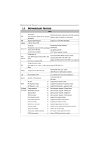
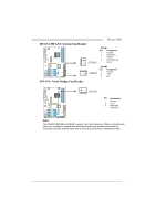
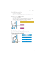
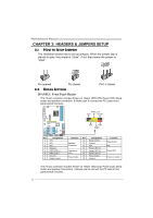
TForce 550 JSFAN1/JSFAN2: System Fan Header JSFAN1 Pin Assignment 1 Ground 2 Smart Fan Control 1 3 FAN RPM rate JSFAN2 sense 3 JSFAN2 31 Pin Assignment JSFAN1 1 2 Ground +12V 3 NC JNFAN1: North Bridge Fan Header JNFAN1 13 Pin Assignment 1 Ground 2 +12V 3 FAN RPM rate sense Note: The JSFAN1/JSFAN2 and JNFAN1 support 3-pin head connector. When connecting with wires onto connectors, please note that the red wire is the positive and should be connected to pin#2, and the black wire is Ground and should be connected to GND. 7
-
 1
1 -
2
-
3
-
 4
4 -
 5
5 -
 6
6 -
 7
7 -
 8
8 -
 9
9 -
 10
10 -
 11
11 -
 12
12 -
 13
13 -
 14
14 -
15
-
16
-
17
-
18
-
19
-
20
-
21
-
22
-
23
-
24
-
25
-
26
-
27
-
28
-
29
-
30
-
31
-
32
-
33
-
34
-
35
-
36
-
37
-
38
-
39
-
40
-
41
-
42
-
43
-
44
-
45
-
46
-
47
-
48
-
49
-
50
-
51
-
52
-
53
-
54
-
55
-
56
-
57
-
58
-
59
-
60
-
61
-
62
-
63
-
64
-
65
 |
 |
TForce 550
7
JSFAN1/JSFAN2: System Fan Header
JSFAN1
Pin
Assignment
1
Ground
2
Smart Fan
Control
3
FAN RPM rate
sense
JSFAN2
Pin
Assignment
1
Ground
2
+12V
1
3
1
3
JSFAN2
JSFAN1
3
NC
JNFAN1: North Bridge Fan Header
Pin
Assignment
1
Ground
2
+12V
3
1
JNFAN1
3
FAN RPM
rate sense
Note:
The JSFAN1/JSFAN2 and JNFAN1 support 3-pin head connector. When connecting with
wires onto connectors, please note that the red wire is the positive and should be
connected to pin#2, and the black wire is Ground and should be connected to GND.