Bosch VC7C1305T Installation Instructions - Page 6
Hardware Installation - camera
 |
View all Bosch VC7C1305T manuals
Add to My Manuals
Save this manual to your list of manuals |
Page 6 highlights
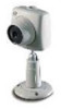
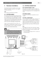
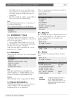
VSS8394/01T Multiplexer | Installation Manual | Chapter 2 EN | 4 2 Hardware Installation 2.2 SYSTEM CONNECTION This chapter describes the installation of the system hardware. For details of operation, see the supplied Operation Instructions. Note Ensure that you read all safety precautions. 2.1 SYSTEM CABLE For the interconnection between the monitor and camera a 15m/45ft system cable is supplied with the camera. For an optimum picture and sound quality you should always use 4-wire dual twisted-pair cable when extending the connection. The maximum allowed cable length is 200m/600ft. Pay attention that the connectors are fixed to the cable corresponding to the figure below. (Figure 2.1) If the length of the system cable is over 200m/600ft (up to 300m/900ft), an interface box should be used to feed the accessory or camera (see optional accessories in the Operation Instructions). Caution The plugs used for the observation system have the same dimensions as standard telephone plugs. (RJ-11) Never connect telephone equipment or cable to the observation system. 2.2.1 Camera inputs (1 to 8) The cameras are connected to inputs 1 through to 8, depending on the number of cameras used. The input is related to the image position (by 3x3 and Quad) on the screen. 2.2.2 Slave output An output for a slave monitor (optional accessory) is available. 2.2.3 Aux. output/input You can configure an auxiliary output configuration via the menu option (see System settings). The auxiliary output provides loop-through from one of the 8 camera inputs or presentation mode where you can connect another video source to aux-in. It is possible to switch between this video source and one of the camera pictures. Note The supplied A/V cable can be used for Aux. output/ input connection. However, if you are using two Video Recorders you will need to order a second A/V cable (see your local supplier). • Connect the Mini Din plug to the Aux. connector of the system monitor. Bosch Security Systems | 2003-06 CAMERA 1..8 TO SLAVE MONITOR 1234 ALARM Figure 2.1 VCR (PLAYBACK ONLY) VIDEO IN AUDIO IN VIDEO OUT AUDIO OUT Not used TV / MONITOR VIDEO OUT VIDEO IN AUDIO OUT AUDIO IN Time Lapse VCR VIDEO IN VIDEO OUT AUDIO IN AUDIO OUT VIDEO OUT VIDEO IN VEXT AUDIO OUT AUDIO IN
-
 1
1 -
 2
2 -
 3
3 -
 4
4 -
 5
5 -
 6
6 -
 7
7 -
 8
8 -
 9
9 -
 10
10 -
 11
11 -
 12
12 -
13
-
14
-
15
-
16
-
17
-
18
-
19
-
20
-
21
-
22
-
23
-
24
-
25
-
26
-
27
-
28
-
29
-
30
-
31
-
32
-
33
-
34
-
35
-
36
-
37
-
38
-
39
-
40
-
41
-
42
-
43
-
44
-
45
-
46
-
47
-
48
-
49
-
50
-
51
-
52
-
53
-
54
-
55
-
56
-
57
-
58
-
59
-
60
-
61
-
62
-
63
-
64
-
65
-
66
-
67
-
68
-
69
-
70
-
71
-
72
-
73
-
74
-
75
-
76
-
77
-
78
-
79
-
80
-
81
-
82
-
83
-
84
-
85
-
86
-
87
-
88
-
89
-
90
-
91
-
92
-
93
-
94
-
95
-
96
-
97
-
98
-
99
-
100
-
101
-
102
-
103
-
104
-
105
-
106
-
107
-
108
-
109
-
110
-
111
-
112
-
113
-
114
-
115
-
116
-
117
-
118
-
119
-
120
-
121
-
122
-
123
-
124
-
125
-
126
-
127
-
128
-
129
-
130
-
131
-
132
-
133
-
134
-
135
-
136
-
137
-
138
-
139
-
140
-
141
-
142
-
143
-
144
-
145
-
146
-
147
-
148
-
149
-
150
-
151
-
152
-
153
-
154
-
155
-
156
-
157
-
158
-
159
-
160
-
161
-
162
-
163
-
164
-
165
-
166
-
167
-
168
-
169
-
170
-
171
-
172
-
173
-
174
-
175
-
176
-
177
-
178
 |
 |