Bowflex Xtreme Assembly and Owners Manual - Page 6
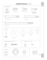
Assembly Guide - parts
 |
View all Bowflex Xtreme manuals
Add to My Manuals
Save this manual to your list of manuals |
Page 6 highlights
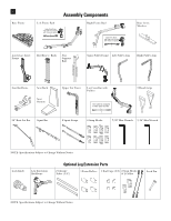
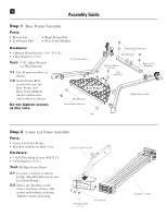
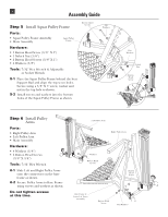
4 Assembly Guide Step 1 Base Frame Assembly Parts: • Base Frame • Left Frame Rail • Right Frame Rail • Rear Cross Member Hardware: • 6 Button Head Screws ( 3/8" X 3/4") • 6 Flat Washers (3/8") Tool: 7/32" Allen Wrench (or Hex Wrench) Left Frame Rail 1-1 Lay all parts on floor as shown. 1-2 Insert Frame Rail connectors into the Base Frame and Rear Cross Member. Secure with screws and washers as shown. Base Frame Flat Washers Do not tighten screws at this time. Button Head Screws Button Head Screws Flat Washers Button Head Screws Flat Washers Rear Cross Member Right Frame Rail Step 2 Lower Lat Tower Assembly Parts: • Lower Lat Tower Frame • Rod Box with Power Rod® Unit Hardware: • 3 Self Threading Screws (#10 X 1") • 3 Flat Washers (1/4") Lower Lat Tower Frame Tool: Phillips Screw Driver 2-1 Lay parts on floor as shown. Firmly slide Rod Box into Lower Lat Tower Frame. 2-2 Fasten the Rod Box to the Lower Lat Tower Frame with screws and washers as shown. Tighten screws until snug. Self Threading Screws Flat Washers Rod Box w/ Rods
-
 1
1 -
 2
2 -
 3
3 -
 4
4 -
 5
5 -
 6
6 -
 7
7 -
 8
8 -
 9
9 -
 10
10 -
 11
11 -
 12
12 -
13
-
14
-
15
-
16
-
17
-
18
-
19
-
20
-
21
-
22
-
23
-
24
-
25
-
26
-
27
-
28
-
29
-
30
-
31
-
32
-
33
-
34
-
35
-
36
-
37
-
38
-
39
-
40
-
41
-
42
-
43
-
44
-
45
-
46
-
47
-
48
-
49
-
50
-
51
-
52
-
53
-
54
-
55
-
56
-
57
-
58
-
59
-
60
-
61
-
62
-
63
-
64
-
65
-
66
-
67
-
68
-
69
-
70
-
71
-
72
-
73
-
74
-
75
-
76
-
77
-
78
-
79
-
80
-
81
-
82
-
83
-
84
-
85
-
86
-
87
-
88
-
89
-
90
 |
 |
