Cisco 2610 Hardware Installation Guide - Page 57
Mounting the Chassis on the Wall, Attaching Rubber Feet to the Router
 |
UPC - 746320089614
View all Cisco 2610 manuals
Add to My Manuals
Save this manual to your list of manuals |
Page 57 highlights
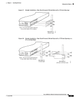
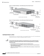
Chapter 3 Installing the Router Setting Up the Chassis To see translations of the warnings that appear in this publication, refer to the Cisco 2600 Series, Cisco 3600 Series, and Cisco 3700 Series Regulatory Compliance and Safety Information document that accompanied this device. Note The screws for attaching the brackets to the rack are not included with the router. Caution Always use two screws to attach each bracket to the rack. After the router has been installed, you must connect the chassis to a reliable earth ground. For the chassis ground connection procedures, see the "Installing the Chassis Ground Connection" section on page 3-13. Mounting the Chassis on the Wall This section explains how to mount Cisco 2600 series routers with a chassis height of 1RU on a wall. Mounting a 2-RU chassis to a wall is not recommended, and brackets are not provided for mounting to a wall. Tip When choosing a wall-mounting location, consider cable limitations and wall structure. Use 19-inch brackets (shown in Figure 3-2) to wall-mount the chassis. The small brackets provide the most stable installation for the chassis. The rubber feet are required to provide spacing between the wall and the router for ventilation and proper cooling. Attaching Rubber Feet to the Router Attach the rubber feet supplied in the accessory kit. See Figure 3-1 on page 3-4 for positioning the rubber feet. Attaching Wall-Mount Brackets to the Router To install the router on a wall, first attach the brackets on each side of the chassis as shown in Figure 3-16, using plastic washers and slotted hex-head screws. Position the washers so that the narrow shoulder faces the router chassis. Note The hex-head screws and plastic washers are used only for wall-mounting the router. For rack-mounting, the brackets are attached using Phillips-head screws, without washers. OL-2171-06 Cisco 2600 Series Routers Hardware Installation Guide 3-11
-
 1
1 -
2
-
3
-
4
-
5
-
6
-
7
-
8
-
9
-
10
-
11
-
12
-
13
-
14
-
15
-
16
-
17
-
18
-
19
-
20
-
21
-
22
-
23
-
24
-
25
-
26
-
27
-
28
-
29
-
30
-
31
-
32
-
33
-
34
-
35
-
36
-
37
-
38
-
39
-
40
-
41
-
42
-
43
-
44
-
45
-
46
-
47
-
48
-
49
-
50
-
51
-
 52
52 -
 53
53 -
 54
54 -
 55
55 -
 56
56 -
 57
57 -
 58
58 -
 59
59 -
 60
60 -
 61
61 -
 62
62 -
63
-
64
-
65
-
66
-
67
-
68
-
69
-
70
-
71
-
72
-
73
-
74
-
75
-
76
-
77
-
78
-
79
-
80
-
81
-
82
-
83
-
84
-
85
-
86
-
87
-
88
-
89
-
90
-
91
-
92
-
93
-
94
-
95
-
96
-
97
-
98
-
99
-
100
-
101
-
102
-
103
-
104
 |
 |
