Cisco CP-7942G Administration Guide - Page 41
Providing Power to the Cisco Unified IP Phone - poe
 |
View all Cisco CP-7942G manuals
Add to My Manuals
Save this manual to your list of manuals |
Page 41 highlights
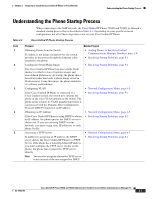
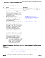
Chapter 2 Preparing to Install the Cisco Unified IP Phone on Your Network Providing Power to the Cisco Unified IP Phone You can resolve these issues by isolating the voice traffic onto a separate VLAN. The switch port that the phone is connected to would be configured to have separate VLANs for carrying: • Voice traffic to and from the IP phone (auxiliary VLAN on the Cisco Catalyst 6000 series, for example) • Data traffic to and from the PC connected to the switch through the access port of the IP phone (native VLAN) Isolating the phones on a separate, auxiliary VLAN increases the quality of the voice traffic and allows a large number of phones to be added to an existing network where there are not enough IP addresses for each phone. For more information, refer to the documentation included with a Cisco switch. You can also access switch information at this URL: http://cisco.com/en/US/products/hw/switches/index.html Related Topics • Understanding the Phone Startup Process, page 2-7 • Network Configuration Menu, page 4-5 Providing Power to the Cisco Unified IP Phone The Cisco Unified IP Phone 7962G and 7942G can be powered with external power or with Power over Ethernet (PoE). External power is provided through a separate power supply. PoE is provided by a switch through the Ethernet cable attached to a phone. Note When you install a phone that is powered with external power, connect the power supply to the phone and to a power outlet before you connect the Ethernet cable to the phone. When you remove a phone that is powered with external power, disconnect the Ethernet cable from the phone before you disconnect the power supply. The following sections provide more information about powering a phone: • Power Guidelines, page 2-4 • Power Outage, page 2-4 • Obtaining Additional Information about Power, page 2-5 OL-15483-01 Cisco Unified IP Phone 7962G and 7942G Administration Guide for Cisco Unified Communications Manager 7.0 2-3
-
 1
1 -
2
-
3
-
4
-
5
-
6
-
7
-
8
-
9
-
10
-
11
-
12
-
13
-
14
-
15
-
16
-
17
-
18
-
19
-
20
-
21
-
22
-
23
-
24
-
25
-
26
-
27
-
28
-
29
-
30
-
31
-
32
-
33
-
34
-
35
-
 36
36 -
 37
37 -
 38
38 -
 39
39 -
 40
40 -
 41
41 -
 42
42 -
 43
43 -
 44
44 -
 45
45 -
 46
46 -
47
-
48
-
49
-
50
-
51
-
52
-
53
-
54
-
55
-
56
-
57
-
58
-
59
-
60
-
61
-
62
-
63
-
64
-
65
-
66
-
67
-
68
-
69
-
70
-
71
-
72
-
73
-
74
-
75
-
76
-
77
-
78
-
79
-
80
-
81
-
82
-
83
-
84
-
85
-
86
-
87
-
88
-
89
-
90
-
91
-
92
-
93
-
94
-
95
-
96
-
97
-
98
-
99
-
100
-
101
-
102
-
103
-
104
-
105
-
106
-
107
-
108
-
109
-
110
-
111
-
112
-
113
-
114
-
115
-
116
-
117
-
118
-
119
-
120
-
121
-
122
-
123
-
124
-
125
-
126
-
127
-
128
-
129
-
130
-
131
-
132
-
133
-
134
-
135
-
136
-
137
-
138
-
139
-
140
-
141
-
142
-
143
-
144
-
145
-
146
-
147
-
148
-
149
-
150
-
151
-
152
-
153
-
154
-
155
-
156
-
157
-
158
-
159
-
160
-
161
-
162
-
163
-
164
-
165
-
166
-
167
-
168
-
169
-
170
-
171
-
172
-
173
-
174
-
175
-
176
-
177
-
178
-
179
-
180
-
181
-
182
-
183
-
184
-
185
-
186
-
187
-
188
-
189
-
190
-
191
-
192
-
193
-
194
-
195
-
196
-
197
-
198
-
199
-
200
-
201
-
202
-
203
-
204
-
205
-
206
-
207
-
208
-
209
-
210
 |
 |